If we consider the cross section of the sail, you will notice that it is also concave-convex plate with a round or oval bulge — mast. The profile of this type is extremely unsatisfactory works on acute courses and sometimes makes impossible the movement close to the direction “head to wind” (nose to the wind): is the failure of the flow, accompanied by zapalskiene sails and almost complete loss of thrust it Should be noted that the situation is changing on a full course — when the wind blows from the side, side back, and back. In this case, the sail is clearly more efficient wing. However, if the wing is not mechanized.
The first attempts to create a new type of sail with characteristics similar to the wing on the sharp course and the sail — in full, taken almost two decades ago. The front edge of it was herself profiled rotating mast, the cross section of which resembled an aircraft wing profile. In likas mast was inserted a narrow sail through reinforced armor. This ending and the mast itself had almost the same chord, and the whole system, in fact, was a wing with a flexible flap. She had already had a number of advantages, but it was a forced option, as inhibited to regulations that existed at the time for some classes of catamarans and ice boats.
Buer with mechanized sail-wing:
1 — weight (steel sheet thickness 3 mm), 2 — mast (dural tube Ø 40Х1,5 mm), 3 — crispity, 4 — cables (steel cable Ø 5 mm), 5 — forestay (steel cable Ø 5 mm), 6 — wing, 7 — flap 8 — power steering device, 9 — seat 10 — body-fairing (plywood thickness 3…4 mm), 11 — a back ridge, 12 — rotating plug rear steering of the skate, 13 — plug the front of the skate, 14 — front strong point, 15 — cross beam.
Therefore, it seems logical transition to a entirely rigid mechanized wing according to the type of aircraft, with a rigid flap, significantly increasing the ratio of “lifting” the forces of the sails at high angles of attack and, therefore, in all courses.
Wing flaps:
1 end rib of the wing (plywood thickness 10 to 12 mm), 2 — longeron (pine slats 20Х60 mm), 3 — the front edge (pine rail with cross section 30X30 mm), 4 — rib No. 7 and No. 8 (plywood 5 mm thick), 5 — reinforced rib No. 6 (plywood with a thickness of 10…12 mm) 6 — rear wall of the wing (the pine Board thickness 20 mm), 7 — a short rib No. 2-5 (plywood 5 mm thick), 8 — shortened root rib (plywood 12 mm thick), 9 — root rib of the flap (plywood 12 mm thick), 10 — rib No. 2-5 of the flap (plywood 5 mm thick), 11 — front edge of the flap (pine bar section 40X60 mm), 12 — internal brace wing (nylon or linen twine, steel wire Ø 0.3 mm), 13 — diagonal element of the flap (plywood 5 mm thick), 14 — trailing edge flaps (pine rail cross-section 20X50 mm) 15— the rear edge of the wing (pine rail section 20Х50 mm), 16 — braces of the spar (pine slats with cross-section 20X20 mm), 17 — fairing (plywood 5 mm thick), 18 — end rib of the flap.
Initially it was assumed that the rotary flap will be on the entire length (or rather height) of the wing-sail. However, it appeared that much more profitable, so that the flap was only about 60% of the height of the wing. The fact that the characteristics of the wind at different levels is uneven: at the bottom its speed is somewhat less than the height of several meters, moreover, changes his vector. This means that the angle of attack of the root portion of the sail-the wing relative to the direction of the apparent wind will be greater than its end parts. Ideally, it would be nice to have a “fractional” flaps across the wing span, consisting of several sections, deflected at different angles, However, almost proved to be quite sufficient to equip only the lower flap part of the wing.
All these considerations formed the basis for the design of Buer from the hard mechanized sail-the wing area of 5 m. the Scheme of the glider is quite traditional: three-point design with rear steerable skate. The base of the case is collected from pine planks and plywood frame; plywood and fairing. The crossbeam is also wood — for it will fit straight grained flat Board with a thickness of 60 mm and a length of 3.3 m
The frame will require two longitudinal pine bar section 25X60 mm and a length of 3.5 m and five or six transverse. Top and bottom of the video Assembly are sheathed with plywood with a thickness of 5 mm. Connection of wooden elements is best done on epoxy glue (but appropriate and casein). After curing of the adhesive and processing of the panel outside the contour on it is mounted a bar (steps) of the mast and supporting bar of the steering ridge.
Plywood fairing going on the simplified technology before proceeding on a small model (for example, 1:5) to clarify the configuration of the shell elements, cutting them out of thick paper or cardboard, and then transfer their shape onto the plywood. Next, in the resulting billet along the abutting edges nastelivaetsya in increments of 50-100 mm and a hole diameter of 2-3 mm, then the parts are “sewn” soft copper wire. After connecting such twisting of the blank fairing all joints sealed from the inside with epoxy putty consisting of resin and fine sawdust. Upon completion of curing, the wire is removed outside wire cutters-side cutters and inside the joints pasted two or three layers of fiberglass epoxy resin.
But the fairing is mounted on the base panel, the enclosure outside puttied up and smoothed out. It remains to paste over it with a layer of fiberglass and after finishing putties, and final Stripping of paint synthetic enamel.
Cross beam glider — solid. It is cut from a straight grained Board with a thickness of 60 mm and a maximum width of 320 mm. If you find a section difficult, the beam can be glued from two or three boards of smaller thickness. In finished form it is elliptical in shape and of variable cross section. Panel base beam is attached with four bolts threaded M10 nuts and washers; fixed two extensions of the steel cable Ø 4 mm with standard lanyards. On the ends of the beam are mounted hardpoints skates.
By the way, front skates cushioning: elastic element for them is the very cross beam. Rear driven horse may be also no shock, though his absence is somewhat difficult to control Buer. But, in principle, to podrastaet it is not difficult.
The steering ridge — rope, driven from a control car type. The transmission of torque is done with steel cable Ø 3 mm, passed through the drum Ø 60 mm on the steering column, two pairs of guide rollers and double steering sector Ø 250 mm. the Drum and rollers dural, chiseled.
Swivel sail-wing:
1 — Bicycle sprocket, 2 — mast, 3 — wing, 4 — small volosistaja, 5 — flap 6 — the axis of rotation of the flap, 7 — swivel, 8 — pins cylindrical Ø 6 mm, 9 — thrust bearing (aluminum), 10 — bushing (Teflon, nylon or the PCB), 11 — screw M5 12 — M5 screw.
One of the most difficult structural elements of the Buer is mechanized wing-sail. It is going for the classic “planar” technology. For the beginning to make ribs for six, you will need plywood with the thickness of 5 mm, and three (including the root and end) with a thickness of about 12 mm. To build the profiles of the ribs suggest to use a table of coordinates, each of the values which are expressed in relative units (percentage) of the length of the chord of the profile. To obtain the values for the abscissa and ordinate of the corresponding section of the sail-wing, you need the length of this section is sequentially multiplied by a table value of the coordinates of the profile. It should be noted that for sail-wing of the profile with a relative thickness equal to 10%; it has high quality and works well in a large range of angles of attack.
A table of the coordinates of the profile of the sail-wing.
Longitudinal members of the wing-sails are the spar, toe and trailing edge. In addition, in the area from the first to the sixth rib hits the wall separating the wing to the actual wing and the flap.
Spar is a truss, it is based on the top and bottom shelves (pine slats section 20X60 mm). After Assembly, it is enhanced by front and rear rails-braces that forms a very hard farm.
The leading edge — also pine rail section of 30X30 mm. its Docking ribs is as follows: in the edge under them propisyvayutsya grooves, the toe of each of the ribs thus is truncated, so that after Assembly there was no distortion of the profile.
About the same bump in the rear rib flange and the rear wall of the wing. Here, the depth of grooves needed in 10-15 mm.
Wing Assembly begins with the preparation of the Plaza. On a level floor rascherchivanija planned projection of the sail-wing with the axes of the spars and ribs. Next to the Plaza fixed bottom shelf of the spar, and on it are mounted the ribs and reinforced bead and epoxy glue. Fixing glazing beads — small nails. Next, set the glue on the top shelf of the spar and similarly fit in with the ribs.
Base glider:
1 — cross bar (a pine bar section 20X60 mm), 2 — crossmember mounting steps of the mast (pine bruski section 20X60 mm), 3 — steps (pine 60X80X80 mm) 4 — cross member mount cross beam of Buer (pine bruski section 20Х60 mm), 5 — mount cross beam (pine bruski section 50X60 mm), 6 — 8 — sleepers (pine bruski section 20X60 mm), 9 — cross mount steering ridge (pine bruski section 20X60 mm) 10 — the installation area of the steering ridge (pine 60X80X80 mm) 11 — ending (a pine bar section 60X60 mm), 12 — base covering the hull (plywood 5 mm thick), 13 the side members of the base (pine boards section 25X60 mm), 14 — the forward part of the base (pine bar section 40X60 mm).
Skate glider:
1 — the blade (steel strip with a thickness of 8 mm), 2 — cheek (beech or oak), 3 — the screw of fastening of the cheeks to the blade, 4 — bushing (steel pipe Ø 20Х3 mm, is attached to the blade by welding).
Cross beam yachts.
Making sure that these wing elements are connected without bias, you can move on to assembling the front and rear edges and the rear wall. This operation is done using epoxy putty with resin introduced into the small sawdust or tooth powder. Further, the frame of the wing is fixed at the Plaza so as to prevent warp or distortions. After curing of the epoxy binder is enhanced by the longitudinal braces. Diagonal power elements should be introduced between the ribs, thus substantially increasing the rigidity of the wing under torsion. This is not mandatory braces — you can pull vnutritrekovye stretch of durable nylon or even linen twine. To ensure uniform tension, it is recommended to do in one thread. The joints of stretch marks with design elements of the wing are fixed with epoxy glue.
About the same going the flap. However, it is arranged not in the example easier wing: two longitudinal elements (front and rear edge), the ribs and diagonal braces. Assembly of the ribs with longitudinal elements with the frame; the diagonal are inserted vraspor, fixation by epoxy adhesive.
The trim of the sail can be very different. The easiest way to cover it with percale cover three to four times Amalita, and then nitro. It is better to paste over the wing Mylar film for the “model” technology. How this is done, you can learn from publications of the journal “modelist-Konstruktor”. Finally, fit the casing of airtight fabric, such as Bologna or technical type “500”.
Similarly performed and the flap. It is suspended to the wing on two makeshift hinges so that the axis of rotation of the flap coincides with the plane of the chords of the wing.
Mechanized sail has the ability to rotate about a fixed mast, which is a dural tube 40Х1 Ø 5 mm (you can use sports jump pole; wooden version should have increased the base diameter of 50 mm). This wing rests on a thrust bearing fixed to the mast. To facilitate turning the sails into the root rib is mounted the support sleeve fashioned from nylon, Teflon or textolite.
When you rotate the wing relative to the housing hinged flap is automatically deflected in the opposite direction. This is achieved thanks to the installed on the mast and flap velosezon with a ratio of about 1.5, kinematically associated roller chain. The angle of rotation of the flap is approximately one and a half times greater than the deflection angle of the wing. It should be noted that this angle and hence the gear ratio of a chain drive — is chosen empirically. By the way, it makes sense to install asterisk on the mast is not hard, and using a simple lock — for example, a threaded stud with a handle. This will allow you to configure the wing-sail on the conditions of movement rate and wind speed.
Recommend to read HOME HEAT STABILIZER We offer homemade household heat stabilizer can be used in incubators, dryers, fruit, mini-greenhouses etc. From existing analogues it is original schematic construction, maintaining the... PIONEER RACING In this competition almost everything was as really big car races: clearly marked and numbered paths, a huge inscription "Start" and "Finish" bright lights, signal lights, gambling,... 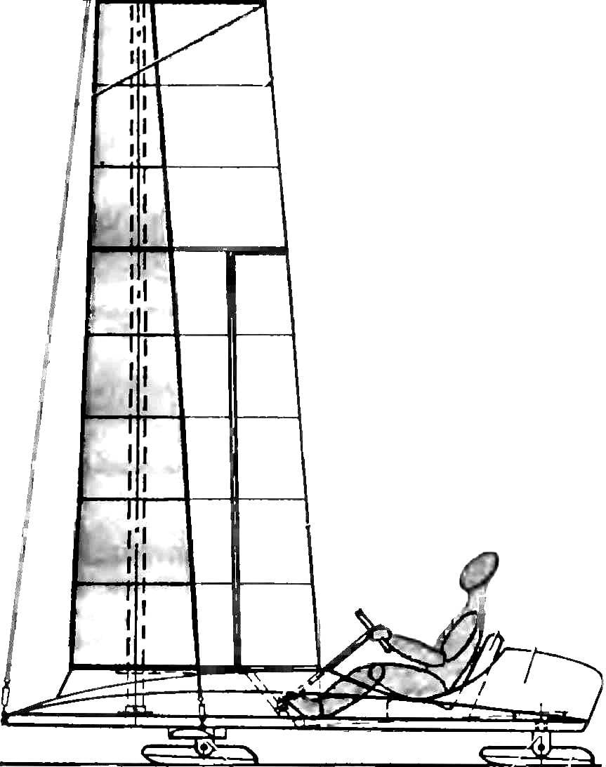
 The question posed in the title, still have not found a final resolution. The first experiments to replace the traditional sail is a vertical wing, by profiling and design friends of the aircraft, did not bring the expected result. The fact that hundreds of years of its existence, the sail turned into a beautiful multi-device for conversion of wind power into thrust, informing the movement of the ship or the Buer. And it works quite effectively, and acute course, with strong and weak wind, his smooth flow and in the squalls. In addition, the sail is a great tool that allows the helmsman to accurately adjust it in accordance with the selected rate and direction of the wind, its force arising from the roll of a sailboat and other motion parameters.