BOW BOSS REZINOMOTORNAYA MODEL

BOW-BOSS REZINOMOTORNAYA MODELAthletes, acting in competition with rezinomotornaya models it is well known the importance of precise trouble-free operation of the stopping device of the nasal boss. Therefore, the appearance of any new construction is of great interest to modelers.
Today we offer our readers the boss, developed by the engineer V. by Anikin from Rybinsk.
 
All the design features of the boss shown in the drawing, they can easily “take” him. So talk about how to work with a boss at the start.
 
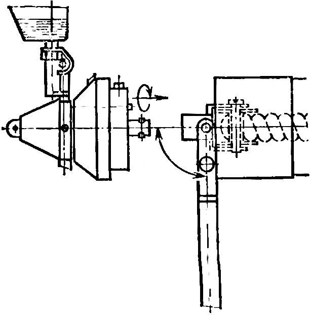
First detach it from the plug (Fig. 1) into the hole where you insert the spring loaded hook drill. The roller 18 touches the end of the rubber motor. After his “starting” drill with a hook is deployed to the 90° and ubiraem much of the forward fuselage (Fig. 3). In the hole Ø 4.5 mm and the notched grooves of the plug is inserted the shaft end of the boss and fix it by turning in the direction opposite to the rotation of the propeller. Pressing the button of the hook, detach the drill. The nasal boss (in the locked position of the propeller) are inserted into the fuselage.
Fig. 1. Bow boss rezinomotornaya model
Fig. 1. Bow boss rezinomotornaya models:
1 — Kok (D16T), 2 — stem nut, 3 — spring (wire Ø 0,4 OBC), 4 — blade propeller, 5 — screw (M3 — steel) 6 — lock nut (M3), 7 — ring, 8 — axis (wire Ø 2 OVS), 9 — rubber ring 10 — hub, 11 — the lever (D16T), 12 — pin (wire OVS Ø 1), 13 — screw (M2,5), 14 male (D16T), 15 — spring (wire Ø 0,3 OBC), 16 — lock, 17 — building (D16T), 18 — movie (D16T, ebonite), 19 — screw (M2,5), 20 male, 21 — bondage (D16T), 22 — pin (wire OVS Ø 2), 23 — threaded sleeve, 24 — shaft (wire Ø OVS 3), 25, 26 — sleeve (D16T), 27 — the bearing № 23 (3Х10Х4), 28 — screw (M1,4), 29 — a cover (D16T), 30 — flange 31 — bushing (bronze), 32 — screw (M1,4), 33 — pin (wire Ø 2 OVS), 34 insert (D16T), 35 — pin (wire Ø 0,8 OBC), 36 — fairing (D16T).
 
For the plant of the rubber motor at the start during the long wait it is necessary to press the lever 11 to the forward position (along arrow B) and rotate the propeller at a certain angle, then release the lever. When this spring-loaded stopper 16 will slide on the end face of the flange 30 before entering the lock hole. The rubber motor in this case tighten up one turn. If you want to make twist by a few turns, the operation is repeated several times.
 
Fig. 2. Winding the rubber motor with removed propeller
Fig. 2. Winding the rubber motor with removed propeller:
1 — hook drills, 2 — button hook drill 3 — the nose of the fuselage.
 
Fig. 3. The connection of the nasal boss after winding the rubber motor
Fig. 3. The connection of the nasal boss after winding the rubber motor:
1 — the nose of the fuselage, 2 — hook drill.

 
At the time of launch of the model hub 10 of the propeller together with the spinner 1 is fed forward (arrow b), 2.5—3 mm, in this position, the stopper 16 is no longer working. The spring 3 is compressed and is retained almost to the last revolutions of the rubber motor due to the friction forces arising from the torque which is transferred from roller 18, the plug 20, the pin 22, the threaded sleeve 23 and 2 (with groove), shaft 24, pin 33, Kok 1 on the hub 10 of the propeller. When the torque drops to near zero, the spring 3 returns the COC 1 and the hub 10 to its original position and tightened up the stopper 16 provides a smooth locking of the propeller in the correct position. The length of the springs 3 and 15 should be specified in the sampling operation of the nasal boss, with the axial force of the first spring should be slightly larger (0.1 kg) of axial force for the second spring. If needed the length can be shortened by grinding the ends on an emery wheel.
The blades of the propeller are formed under the action of air flow and with the rings 9 made of round Hungarian rubber.
 
The propeller blade is made of balsa. In the butt of the blank and glued a wedge of lime paste, which, in turn, based on epoxy resin planted a pointed steel rod with thread M3 (Fig. 4).
 
Fig. 4. The butt of the blade
Fig. 4. The butt of the propeller blade:
1 — blade propeller, 2 — insert from basswood, 3 — steel rod with thread M3, 4 — threads with glue.

 
All titanium parts of the nasal boss can be successfully replaced steel with appropriate heat treatment. The weight of the structure (with the blades of the propeller) 39-42 g.
 
This boss with a few modifications (highlighted in drawing) was operated for several years and has shown himself to be dependable and reliable.

Recommend to read

  • THE BED-INVISIBLETHE BED-INVISIBLE
    THE MYSTERY OF MY GRANDMOTHER'S TRUNK. Looking at it, you can assume anything you want, but not what is hidden inside... the bed. Here rises and becomes a headboard cover, opening rolled...
  • THE FIRST STEP INTO THE PROFESSIONTHE FIRST STEP INTO THE PROFESSION
    The first time I saw this unusual rocket in 2007 in the championship of Russia in Orel. At the start of class models Ѕ4А my attention was drawn to the flight of the rocket glider...