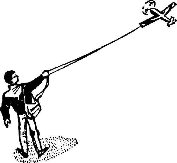
A great many of the problems faces by the Modeler, decided to pursue aviation equipment driven by electric motors.
One of the most important and the primary task — the selection of the motor. After all, it ultimately specifies requirements for the design of the microplane and determines its flight characteristics. And the selection among available brands of engines is extremely limited. Industrial designs a low power, heavy, not allow significant overload required to increase the specific installation data.
The most acceptable solution is a fundamental alteration of the serial microelectrodes from toys. The proposed simple method of becoming widespread of the motor, DI-1-2 is lightweight and powerful enough model aircraft engine.
To start, cut the rear part of the metal shell, leaving a “Cup” with a height of 15-16 mm. “the Bottom” is made easier by cutting out two Windows. The result should remain the only jumper with a width of 5-6 mm holding the front bearing of an anchor. The meaning of this operation is not only removal of excess mass. More important to ensure good cooling when the engine is loaded, which is achieved with the broad Windows of the entrance of cooling air.
Then, in a lightweight package by soldering are fixed four pins for attachment of the brush unit. Two of them (7a) soldered in the middle of the locations of the permanent magnets, but exactly in between two pins (7b). It should be noted that the delays “a” (material is all the same — OVS Ø 1.5 mm) have a length of 18 mm and must be from the body 11 mm, and the details of the “b” with a length of 23 mm by 14 mm. To the ends of pin “b” is soldered tin rear rack, load bronze bushing-bearing. Don’t forget: to mount the rack only after the installation is ready the anchor!
Fig. 1. Modified microelectronical D-1-2:
1 — propeller shaft, 2 — Bush-bearing, 3 — bearing gear, 4 — gear, 5 — Bush-bearing, 6 — engine block, 7a—7b, the hinge pins of the brush unit, 8 — insulation, 9 — armature shaft, 10 — anchor 11 — impeller-heat, 12 — the collector node 13 — bushing brush holder, 14 — brush holders, 15 — bearing anchors, a 16 — rear rack, 17 — pinion, 18 — front bearing armature 19 — front, 20 — textolite rings 21 of copper-graphite brushes, 22 — insulating bushing of the collector 23 is a wire fastener holder, 24 — standoffs.
Fig. 2. The placement of the pins on the engine block.
Completion of the anchor is the alteration of the collector unit. Staff need only plate collector, although they are useful to make a new, thicker copper (0.6 mm) — fine quickly be out of business. Plate using epoxy mounted on a textolite bushing with a length of 7 mm and Ø 3.5 mm with internal hole Ø 2 mm Textolite rings-hoops with the resin finally link the node into one. After crimping of the collector onto the shaft to him podpisatsja the ends of the armature and the petals of the impeller-heat sink made of sheet copper with a thickness of about 0.1 mm.
Fig. 3. The collector node.
Fig. 4. The engine Assembly.
The brush holders are made of hard copper plate or of hard brass with a thickness of 0.2 mm. Width of ribbon stock 2.5 to 3 mm. the ends of the brush holders are short sleeve with which these curved plates are mounted on pins with wearing them on the tubes-insulators. The brushes are cut from a larger odnogrupnikov. Fixing of brush holders alone soldering is not sufficiently reliable due to high temperature loads. To increase the reliability of connection allows additional binding wire and propeica nodes. Finished parts are mounted on the pins from the longitudinal shear them protect short sections of rubber nipple (standoffs).
For reducer need to pick up a small gear from micro mechanics or unnecessary alarms. The optimal ratio of the number of teeth is 9 to 20 or 9 to 24. Drive gear tightly mounted on the armature shaft and counter shaft (gear wheel) together with a soldered shaft is mounted in bushings-bronze bearings. The front bearing is fixed by soldering on the support gear (OVS wire Ø 1.5 mm, solder on the motor housing) and rear — on the front of the motor.
Checking the ease of rotation of the elements of the plant, rolled down the collector node for small currents. Then you can put the propeller and to check the operation under load. In the proposed variant of the installation with propeller Ø 144 mm (two-bladed) develops a static thrust exceeding 70 GS at a voltage of 16 V and the consumed current of 2-2. 5 A. the mass of the plant complete with spinner and propeller 40 g that allows for this power to use it for many aircraft models.
Y. ZDANOVICH, Lviv
Recommend to read ADJUSTABLE POWER… A simple power control of the load can be made from industrial phase speed controller electric BUE-ЗВР1. This device has small dimensions 50x55 mm, excluding handles and a reversible... FOR COMBAT AND AEROBATICS Universal control line model aircraft. The design "Teardrop" models for air combat — have occurred in several stages. In fact, immediately, in one step to create obedient to the pilot...  A great many of the problems faces by the Modeler, decided to pursue aviation equipment driven by electric motors.
