
 For the computer control various devices and objects I propose to use the method of pulse width modulation (PWM) is equally successful when working with different PCs: Intel-80286 to Pentium latest modifications. Perhaps, the only condition — the presence of a free com port. The relationship with him is up to 200 m can even be done through conventional telephone wires, no protection against the electromagnetic effects of the environment. In the transition to the more sophisticated, shielded lines of the “range” computer control with PWM increases.
Multi-channel load (e.g., light displays, or is armed objects) obeys the impulses coming from the PC through the com port, with two fixed durations (10 and 90 MS), indicating transmission log.0 and the log.1. Their stability is determined by the internal oscillator of the base computer, and the duration, duty cycle, and the sequence formed by the special program.
The appointment of governors of the PWM signals and their fixation on the shift register К555ИР8 occur in the device, where the switched load is used, the matrix consisting of light emitting diodes of HL1— HL8 (Fig.1). An 8-fold increase in the number of shift registers is obtained, display with 64 channels display the information. But the next step in this direction is impossible without strengthening of the gate signal supplied to the input From all of the registers.
A further limitation is caused by the increase of time of control action. For example, to control a single channel requires the PWM pulse duration of 90 µs, plus another 10 MKS required to discharge timing capacitor C1 and the preparation for the next reception. Total to 100 µs. Accordingly, for the 64 channels will be required of 6.4 MS, and 640 channels is 64 MS. And that’s without taking into account the work of the program!
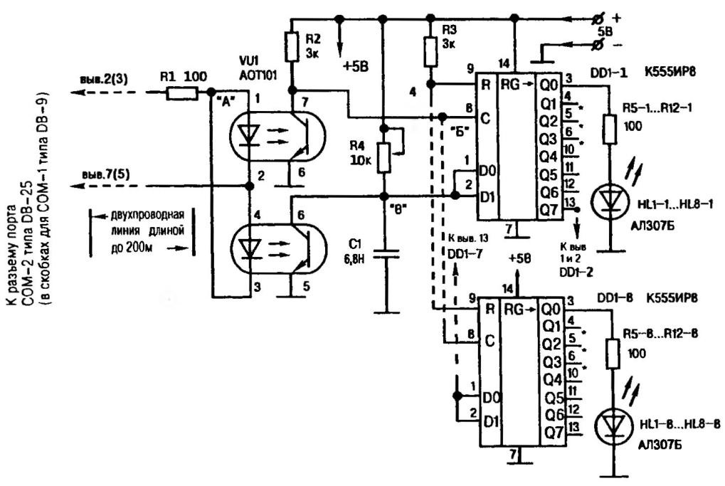
Fig.1. A circuit diagram of the device computer control via com-port matrix scoreboard from led 8N (where N is the number of chips К555ИР8) or other low-power multi-channel load
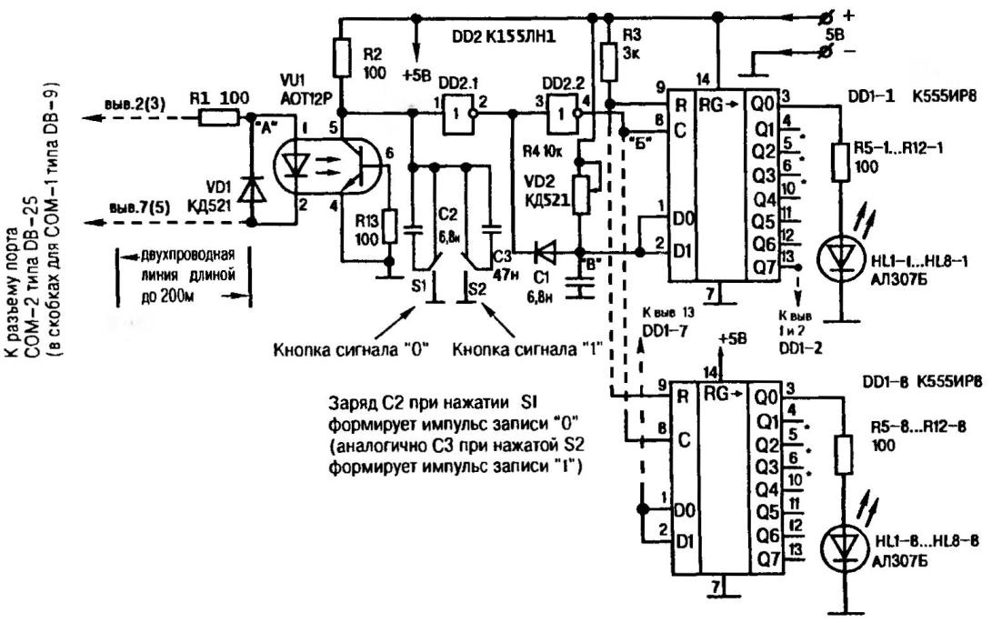
Fig. 2. The same pattern, but the addition of circuit input information manually
In reality, however, the PWM control signal even for a single channel, spent more than 100 µs, and a few more times. Of course, with 64-channel load total duration of issuing control pulses will increase even more, not to mention the 640 channel. With this in mind, we have to go on a trick: when programming to form a first escape sequence in the buffer, and from there to give the buffer to the port.
If the conditions required to maintain control of the load even when the computer is disconnected, it uses a somewhat modified scheme — with chain manual data entry (Fig.2). It is designed so that pressing the button S1 (or S2) unblocking of the capacitor C2 (or C3) and its charge, and hence the formation of the PWM pulse of the appropriate duration, followed a “push” in the shift registers К555ИР8.
Detection of the PWM pulse (with duration of 10 µs and 90 µs) is carried out in both variants of the scheme with the chain of charge of capacitor C1. Upon receipt of the pulse of 10 µs, the capacitor does not have time charged to the level of the log. 1 thus, fixed log. 0. On the contrary, with the arrival of 90-µs signal charge is able to work, so there is a commit log. 1. The discharge is carried out through the Executive chain of optocouplers VU1 (diode VD2 and the output of the logic element DD1.1 in a second embodiment of the diagram). A positive differential voltage clock input is recorded and With the subsequent shift of the received values (1 or 0) the bits of the register.
The duration of the control pulse is selected for the lowest possible com port. Set at 110 KB/s set time unit interval (approximately equal to 10 µs).
When transmitting a signal FF (=1111-1111) is given a starting interval, and 8 of the unit intervals of the signal 1. In the line that goes to 12 V. Thus generates only one pulse — start, which is equal to 10 µs.
Similarly, for the transfer of 90-µs pulse is issued byte 0 (=0000-0000), and the line to the start added another 8 intervals. The result is a 90-µs impulse control. This 9-fold difference in duration is achieved high reliability reading.
With a large removal of the load from the computer or intense interference, it is advisable to go to software increase impulse control. And for error-free selection on the reception — proportionally increase the capacitance of the capacitor C1 (also true for the second variant of the diagram). Note, however, that this will increase the duration of the transmission of control signals. Functional purpose of the variable resistor R4—adjust charge time of this capacitor, that is, adjusting the definition of the definition of signal 1 or 0.
To control more powerful than LEDs, the load in each channel to be installed first, galvanic isolation (for example, using optocouplers АОУ115Г), and secondly, the electronic key of the type of triac. And if you use КУ208Г (Fig. 4), even without the radiator-heat sink it is possible to output 100 watts. Such power is sufficient for switching of incandescent lamps in a matrix scoreboard, powered by a household outlet.
Radio components required for the Assembly of the circuits is not critical to the choice. In particular, the constant resistors of MLT fit and others. Convenient variable resistors SP5-2, and as the buttons S1 and S2 of manual control — switch МП8 or their analogues. Chip К555ИР8 can be replaced by К155ИР8 or similar and put the inverter. It is only important to record and shift was carried out at the end of the control pulse. An appropriate replacement is easy to find and К155ЛН1.
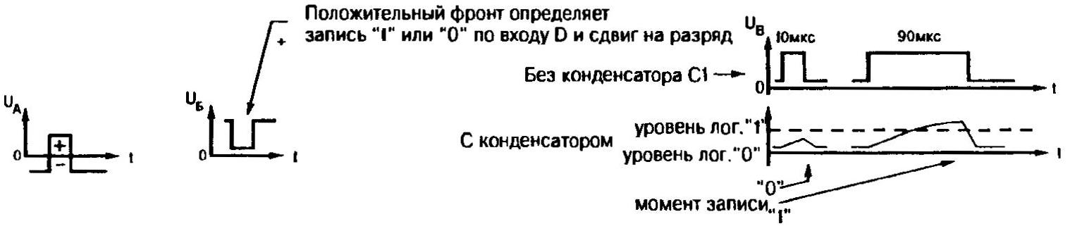
Fig. 3. Stresses at the control points; the output Q1 of each IC is connected to the inputs D0 and D1 as IC (Q1 except the last one)
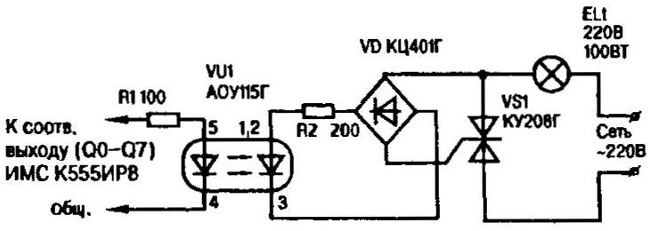
Fig.4. Connect a 100-watt channel (in particular, tungsten) to the scheme computer load control
The performance of each of the schemes can be checked, controlling the oscilloscope passage of pulses at the test points. Then, setting a particular transmission (for example, “Running lights 1 + 1”), to achieve a variable resistor of the correct allocation of the transmitted signals.
Requirements to the Executive circuits in common. They are quite adequately covered in the Amateur literature, so are not listed here.
Now about the program. It is written in basic and allows you to get creative lighting effects using PWM, computer control multi-channel load, e.g., light decoration Christmas trees, advertising boards, matrix boards.
Program control multi-channel load via com port
(language, basic)
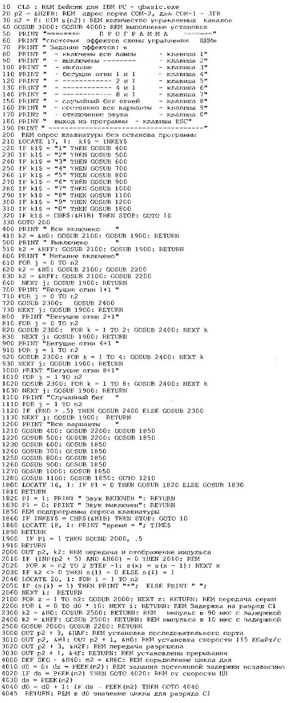
In line 20 sets the number of managed channels (in one case eight, two — sixteen, etc.). If you are using com port 1, in line 10 is called its address, and input the selected variant of the scheme is connected to terminals 3 and 5 of the DB-9 connector of the computer.
For control from other programs with the number of bits up to 64 (eight chips К155ИР8) requires special, bulky enough to program the “Driver”. The author is available, however, publication is impossible due to the limited journal space.
A. SHARONOV, Novosibirsk, Russia
LITERATURE
1. A. Glushchenkov. Help out the FORT,— modelist-Konstruktor, 1999, № 4.
2. A. Glushchenkov. Water “silver” computer — modelist-Konstruktor, 2000, No. 1.
3. A. Sharonov. Capacity — using a com port-2— modelist-Konstruktor, 1998, № 9.
4. A. Sharonov. The survey is conducted by computer. — Modelist-Konstruktor, 1999, № 6.
5. A. Sharonov. The specialist will measure the capacity. — Modelist-Konstruktor, 1997, № 4.
Recommend to read
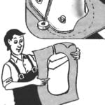 LIKE A COMPASS
When laying linoleum or carpet is often a problem with cutouts in the places where you need to go around the curved area. In these cases, will always help... a small wheel. Attach it... NOT WITH A SLEDGEHAMMER, AND A HYDRO DRILL
Whether there was a need to dig posts to enclose a light fence a garden or summer cottage, or set the pins to maintain young seedlings — not objazatelno to pick up a shovel or a...
