At the time of making this simple watercraft, which is even difficult to name: “either a junk, or a boat, or a boat, or a raft,” I had a “Kazanka” — a spacious, sturdy boat. However, it was intended for sailing with an outboard motor. But what kind of fishing, tell me, in a quiet backwater after a motorboat has entered it. For rowing, the “Kazanka” is rather heavy and unwieldy. Delivering it to the water area is also a troublesome task — it was impossible to do without a trailer and an assistant.
So I decided to make a smaller boat, but lighter and more maneuverable. Suitable material for it was available: for several years a large duralumin sheet had been stored under the garage roof, and I simply couldn’t bring myself to cut it into pieces for small items. It (2700 mm long, 1800 mm wide, and 2 mm thick) largely determined the boat’s design, its dimensions and lines.
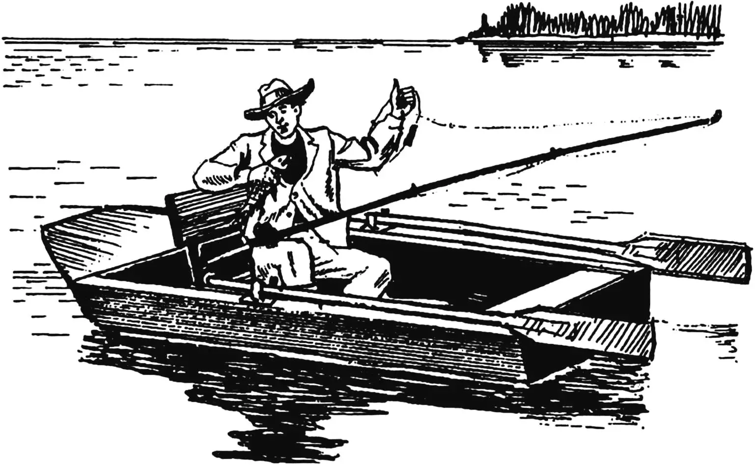
I took as a prototype a small vessel called a “jonboat” (probably for its simultaneous external resemblance to both a two-transom Chinese boat — a junk, and a port workhorse — a boat). These vessels are very stable and have significant load capacity, which was what I needed first and foremost.
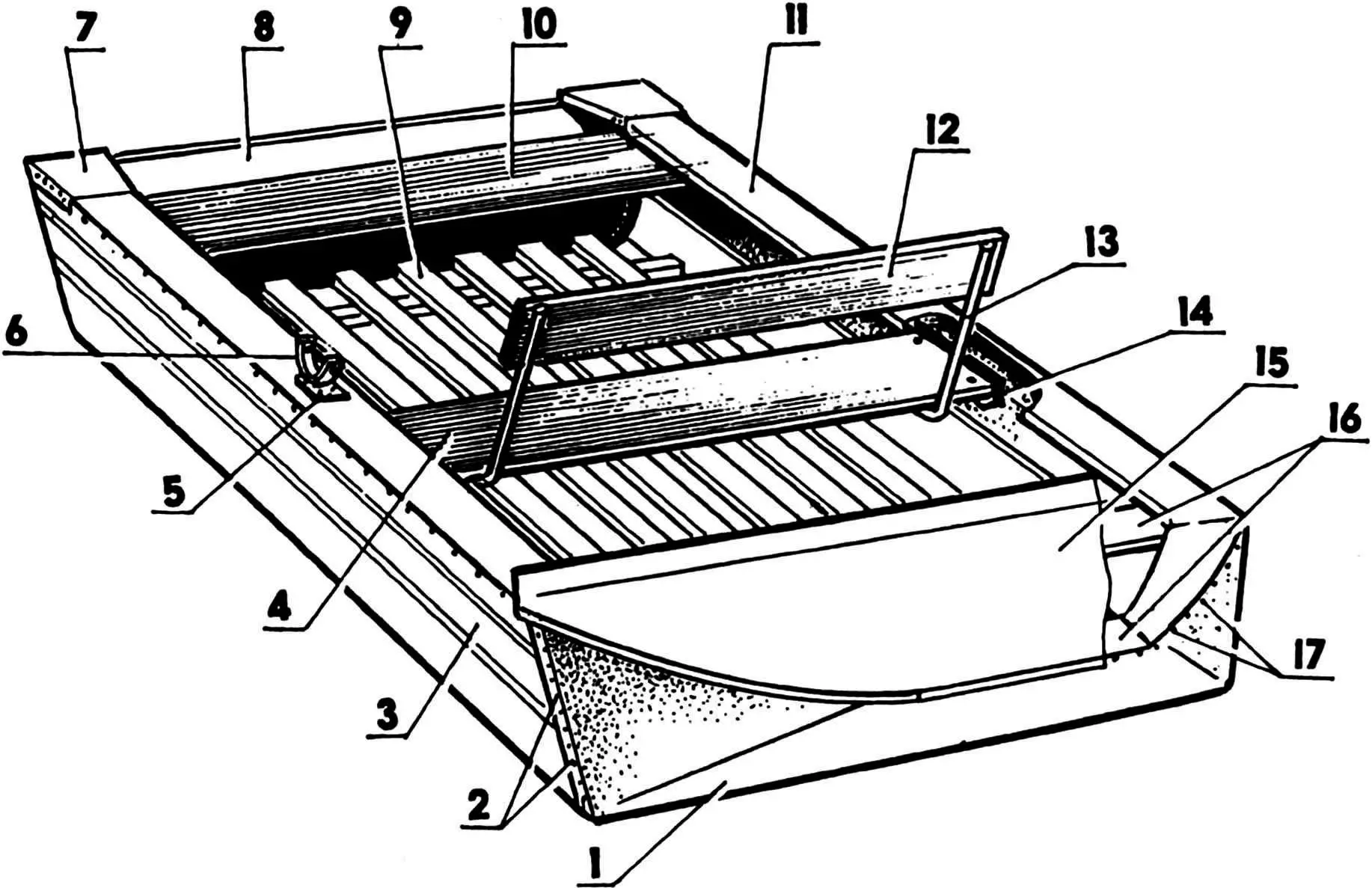
1 — front transom; 2 — rivets (aluminum Ø3, on site); 3 — side; 4 — rower’s seat (hardwood board s20); 5 — plate (St3, sheet s2, 2 pcs.); 6 — oarlock (St3, sheet s4, rod Ø10, 2 pcs.); 7 — gusset (duralumin, sheet s1.5, 2 pcs.); 8 — rear transom (duralumin, sheet s5); 9 — floorboard (hardwood block 40×20); 10 — passenger seat (hardwood board s20);
11 — gunwale (spruce board s15, 2 pcs.); 12 — rower’s seat back (hardwood board s20); 13 — back support (duralumin, tube Ø22, 2 pcs.); 14 — seat mounting bracket (duralumin, angle 40×25, 4 pcs.); 15 — deck planking (duralumin, sheet s1.5); 16 — beams (spruce board s15); 17 — galvanized nails
I designed the boat based on the dimensions of the available metal sheet. I set the side height at 350 mm (I read somewhere that this is the minimum allowable), and the front transom length at 600 mm, which corresponds to an angle of its inclination to the water surface of approximately 35°. And although cutting the metal sheet seemed straightforward, after making sketches of the future boat and trying to anticipate all the upcoming difficulties, I made a mock-up of it from a rigid cardboard sheet.
In the boat’s construction, I used the duralumin sheet as both sides and bottom. At the same time, it is a load-bearing element, since there is no conventional power set of frames and stringers in the boat. Only partially their role is performed by two seats and the gunwale. The boat has no conventional stem, and no keel as such, since it is practically flat-bottomed, and its sides in front do not converge at the stem, but transition into an inclined trapezoidal transom.
The advantages of boats with duralumin sheathing are well-known and are evident even on shore: lightness, strength, durability. And although the latter circumstance was not taken into account (the vessel was made, in general, as a temporary watercraft — until purchasing a good inflatable boat), everything turned out according to the saying: “There is nothing more permanent than temporary” — the boat has been serving for several years now and I’m not planning to disassemble it yet, it turned out to be a very practical vessel. No trailer is needed to transport the boat — it can be quite transported on a roof rack installed on a passenger car. It’s easy to load the boat onto it with two people and even one person can perform the loading. There are no concerns with maintenance and preservation for storage — I put it on its side or on the rear transom, moved it to the wall and let it stand until the next navigation under a canopy, taking up very little space.
On the water, other positive qualities of the boat are revealed: good stability, large displacement (buoyancy), high maneuverability and ease of rowing. Well, such characteristics as speed or course stability at such boat speeds are if not excessive, then certainly not primary, so I neglected them to ensure the other above-mentioned qualities.
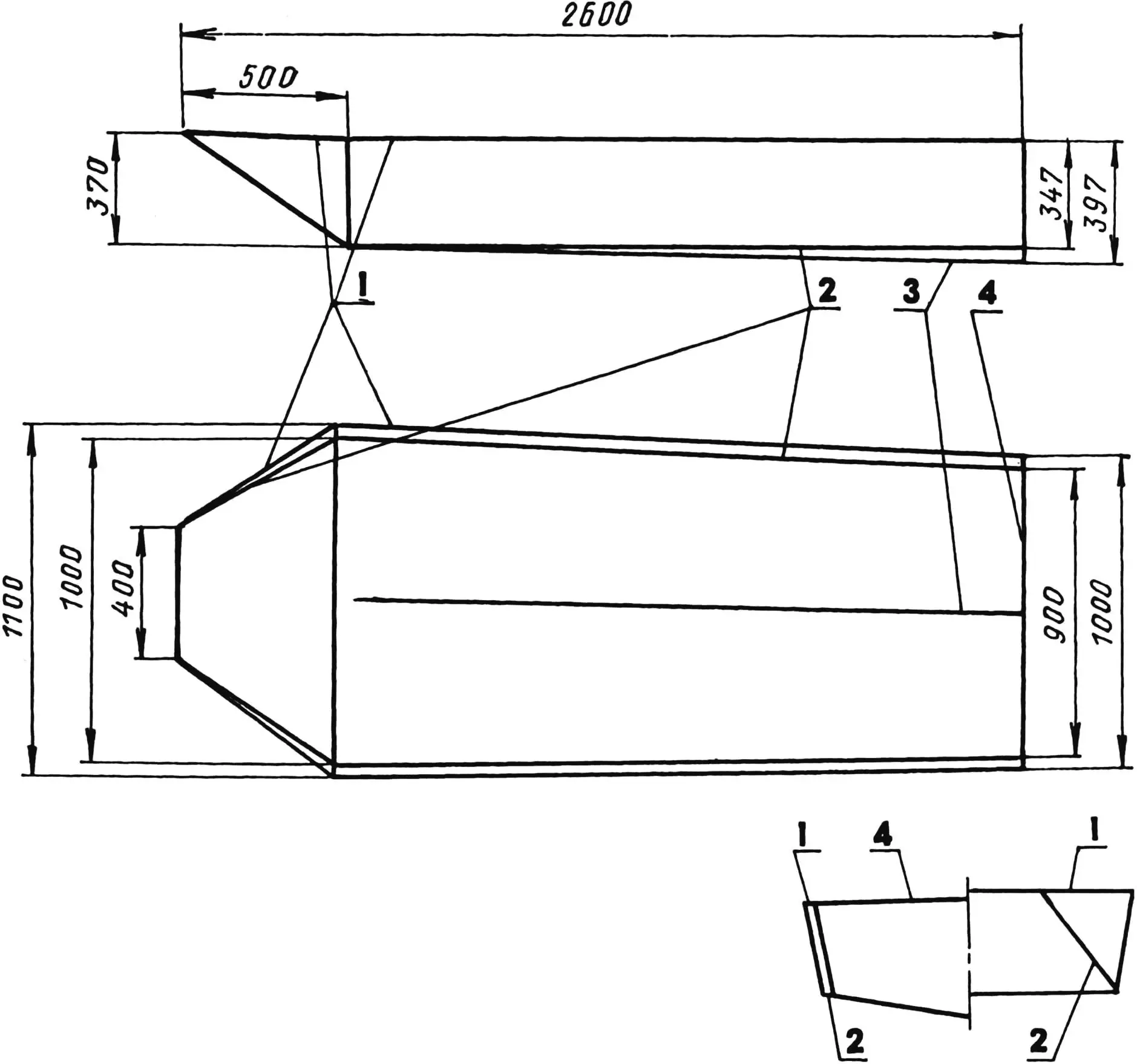
1 — side line; 2 — chine line; 3 — keel line; 4 — transom line
Doubts when working out the design variant arose only when choosing the transverse dimensions: whether to make the sides higher and the width smaller, or vice versa. The choice fell on the “vice versa” option. On those water areas where the boat was to sail — quiet backwaters, calm streams, small lakes, etc., there is no strong current and large waves, which means high sides are not so necessary. But significant width is exactly what is needed. Often when fishing or hunting waterfowl, you have to stand in the boat even at full height.
After making the mock-up, I applied markings to the metal sheet and began cutting it in several steps. I considered the principle “measure seven times, cut once” unacceptable in this matter and used the opposite approach — having measured and marked once, I began cutting the metal first with larger than required allowances, not cutting immediately to the end of the marking lines. Gradually bending and fitting the mating parts to each other, I little by little cut off the allowances and cut the marking lines. I note: this operation is better performed with an assistant.
I made the connection of seams-joints (allowances with the sheet) using aluminum rivets with a semicircular head and a shank diameter of 3 mm. I drilled the corresponding holes for them simultaneously in both connected parts and details on the stern on site in a checkerboard pattern (in two rows). Before riveting, I coated the mating surfaces with thickly ground paint.
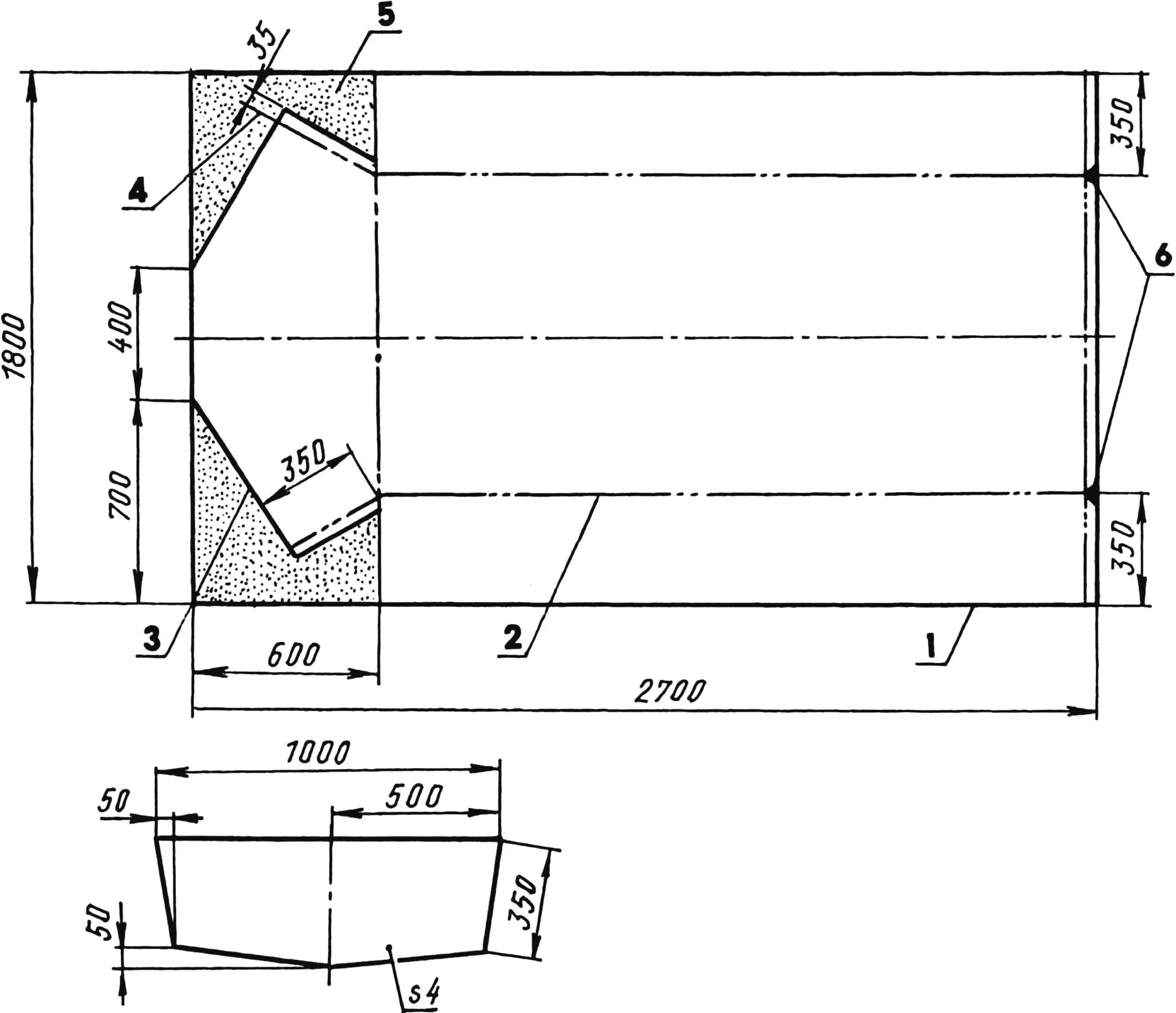
1 — sheet contour lines; 2 — bend lines; 3 — cut lines; 4 — auxiliary marking lines; 5 — removable parts of the sheet (gray color); 6 — removable on-site parts of the sheet (black color); 7 — rear transom (duralumin, sheet s4)
To avoid using material for the transom from this same duralumin sheet, I selected another one — 5 mm thick. This added a bit more riveting work, but the boat’s length turned out to be the maximum possible and now two people with the necessary fishing or hunting equipment can confidently sit in the boat.
Initially, the watercraft was conceived in a very simple form: a hull in the form of a rectangular parallelepiped (with vertical sides) and a bow in front in the form of a prism. However, during hull assembly, even before installing the transom, it was discovered that the boat’s sides were spreading apart (moving away to the sides) under their own weight, and the bottom at the stern was sagging when lifting the hull. At the same time, the boat’s bow was lifting, and the top of the sides in the bow section was rounding. However, all this did not upset me — such changes gave the boat a more attractive appearance. Then I cut the transom not rectangular, but shaped. As a result, the boat acquired slightly flared sides, a raised bow and slight deadrise. The latter, by the way, according to theory, should have improved the boat’s course stability, which happened in operation.
Along the upper edge of the sides, I mounted gunwales from spruce boards with a cross-section of 100×15 mm. On the watercraft, they serve as both stringers and fender rails. In the bow on the front transom, they are connected by a beam — a transverse beam for deck support. In the bow section, the gunwale is made composite due to the large curvature, and pads from the same board are installed and attached under the joints. The sides are nailed to the gunwale along their entire length with galvanized nails. Another beam is mounted between the gunwales at the rear edge of the deck planking, made from 1.5-mm duralumin sheet. The deck edge itself is flanged so that water that gets on the planking drains overboard. At the stern, the gunwales are connected to the sides and transoms with gussets bent from the same 1.5-mm duralumin sheet. Here, on angle brackets riveted to the sides, the passenger seat is installed. In the same way, but only in the middle part of the boat, the rower’s seat is mounted. Despite all the simplicity of the boat’s equipment, this seat has a backrest. But since it only hinders the rower when moving, the backrest folds (tilts forward) and is installed with its back side flush with the seat surface (like on the “Kazanka”). The backrest is raised when the rower is resting or fishing.
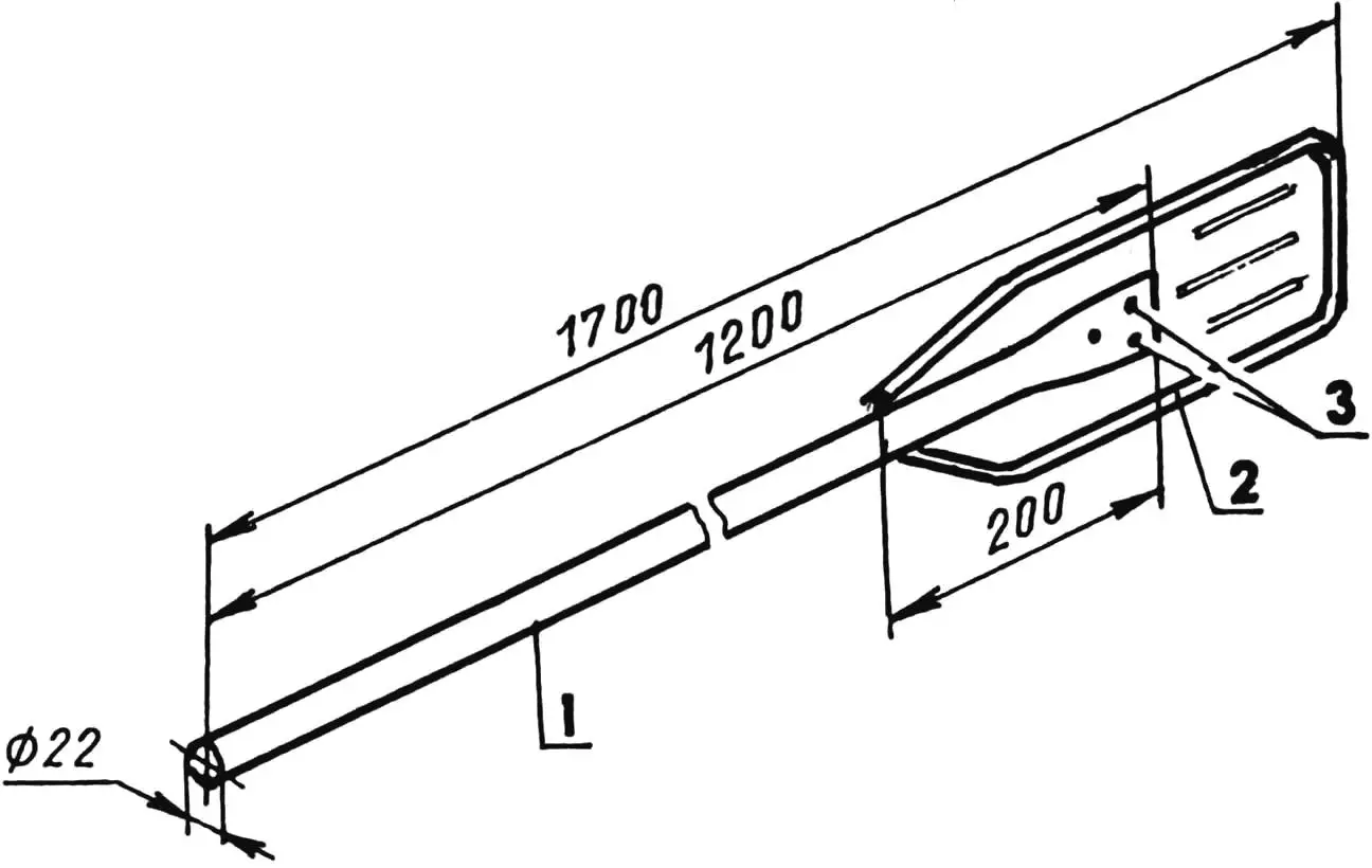
1 — shaft (duralumin, tube Ø22); 2 — blade (duralumin, sheet s2); 3 — rivets (3 pcs.)
And finally. The oars are homemade, although the blades are taken from the oars of the “Kazanka” boat. The shafts are from duralumin tube with a diameter of 22 mm. In the lower part of the tube, they are cut lengthwise in half, the ends are flattened. The blades are inserted into the slots and riveted.
The oarlocks are ordinary two-pronged forks with pins welded to them. The pins are inserted into bushings riveted to the sides under the gunwales. To prevent the holes in the gunwales from wearing out, steel plates are attached to them at this location. The oars in the oarlocks are held by M5 bolts inserted into through holes drilled simultaneously in the fork prongs and shaft tubes.
All wooden parts of the boat are impregnated with hot linseed oil twice, and the hull is painted on the outside with paint in a “protective” color. For the watercraft’s unsinkability, the forepeak (niche under the deck planking) is filled with foam.
Remember your safety: you can only go out on the water in such a boat by wearing an individual flotation device: a vest or chest protector.
«Modelist-Konstruktor» No. 8’2003, E. SEVOSTYANOV
Recommend to read
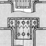 “TRAP” IN THE SINK
I refused to offer the industry's trap — plastic perforated liner at the drain mouth of the shell: it has the shape of a hole and instantly get clogged even debris. Made of a plastic...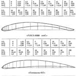 ATLAS PROFILES
PROFILE "NACA-6409". Developed in the early 30-ies in the aerodynamic laboratory of the NAC (USA) for lifting aircraft-biplanes. This profile can be recommended as models of gliders...
