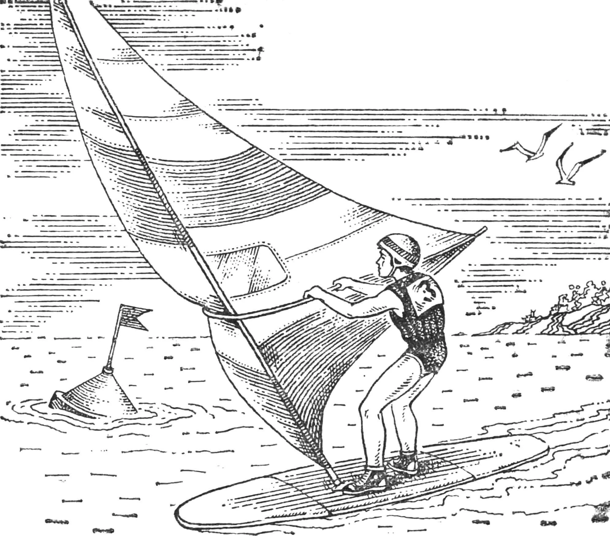
No matter how much we talk about the windsurfer being the smallest sailboat, you still can’t get on a trolleybus with it. To transport a sailboard, you need at least a car. Of course, it is possible to transport a boat about 3.5 m long on public transport, but…
…it would be better if it were collapsible, so that all its elements could be placed in a canvas cover. A package with dimensions of 1.2 x 0.45 x 0.77 m is, of course, quite bulky, but you can get to the reservoir with it without causing fair complaints from fellow travelers. A package of this size will be accepted as luggage even at the airport, not to mention rail transport.
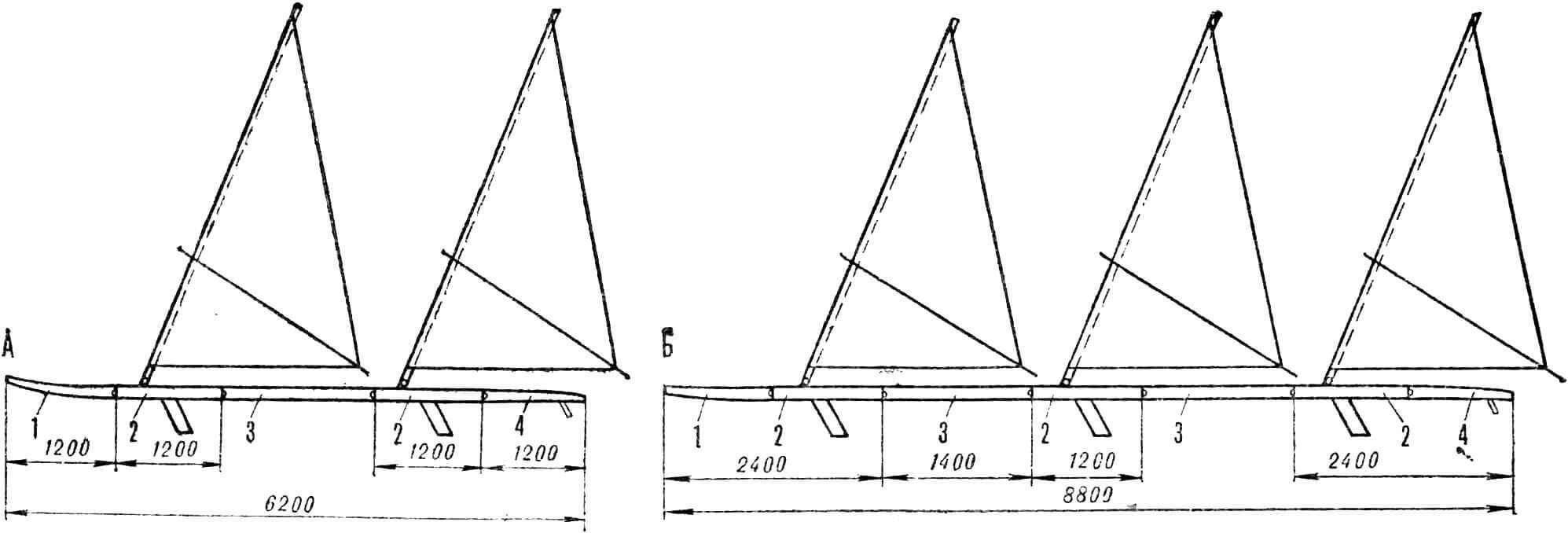
It is necessary to warn: a collapsible sailboard is heavier than a standard one by 4-5 kg due to additional fastening units and intermediate walls, and it is also somewhat more difficult to make. However, if you have a number of similar hulls and several additional 1400 mm sections, then it will be possible to turn a single-masted surfer into a two-masted tandem, the speed of which is significantly higher. But these are not all the advantages. It is just as easy to assemble even a three-masted sailboat from two additional sections molded in the same matrix as the hull and three hulls.
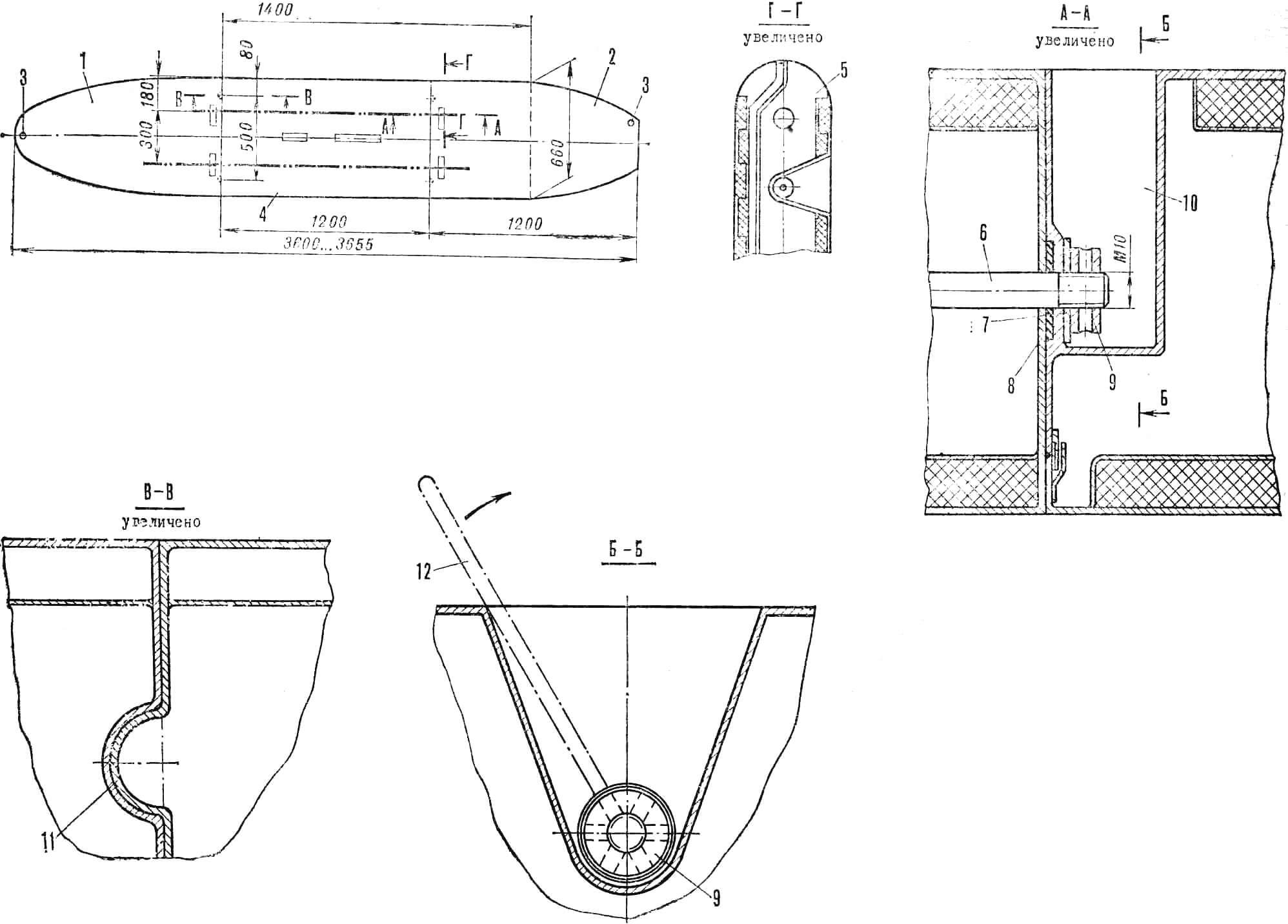
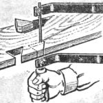
1 — bow section, 2 — stern section, 3 — drain plugs, 4 — central section (dash-dotted line shows location of tie rods), 5 — stern section wall, 6 — stud, 7 — metal washer, 8 — rubber washer, 9 — special tightening nut, 10 — niche for nut, 11 — centering hemispheres, 12 — key: steel rod 200 mm long, Ø 6 mm.
It should be noted that the lines of the collapsible hull are simplified compared to the standard ones – this had to be done for the convenience of assembling the sections. The running characteristics, of course, are somewhat lower, but since the boat can only be considered as a training or pleasure boat, some loss of speed is unlikely to be of decisive importance.
The hull we propose to make has increased stability and load-bearing capacity.
If you have already used our recommendations and saved the matrix for the non-separable case, it is not at all necessary to make a new form for making a sectional board.
MASTER MODEL AND MATRIX
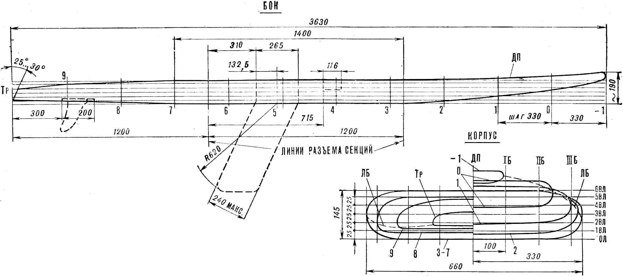
How to make a master model (dummy) from a theoretical drawing was described in sufficient detail in “M-K” (No. 6 for 1980). Only more careful control of the flat sections of the bottom and roundings of the sides is needed. In this case, it is best to use one template for the entire section between the third and seventh frames. Mark the joints with a fishing line laid precisely along them, glued with chlorvinyl insulating tape. Carefully ensure that the dimensions of the 1200 and 1400 mm sections are strictly maintained, and that the sections are perpendicular to the hull axis. In the same way – with a fishing line and insulating tape – mark the LNSH on the dummy. Later, these marks will be imprinted on the matrix, which will significantly facilitate the installation of technological partitions for forming the intermediate walls of the sections.
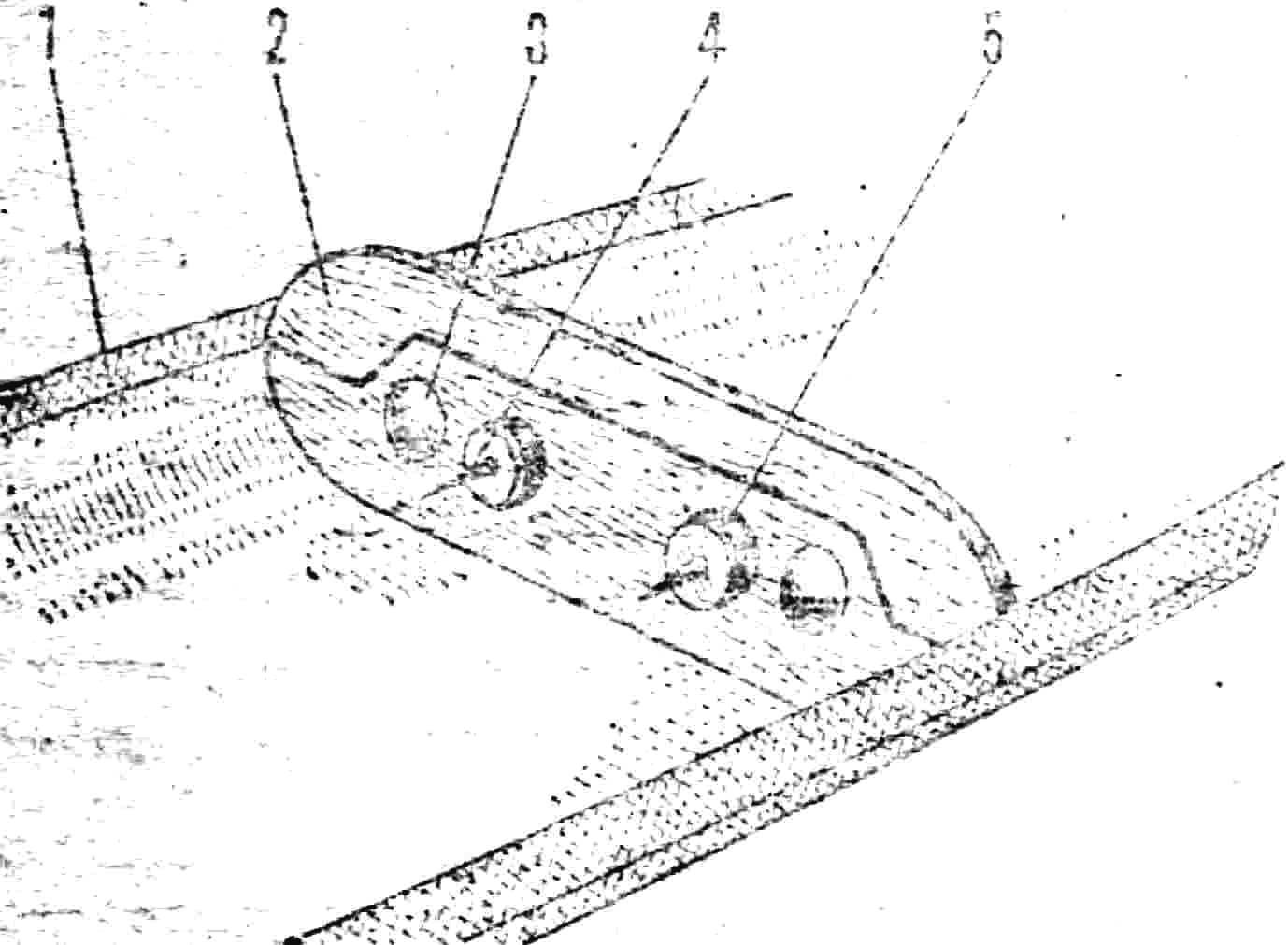
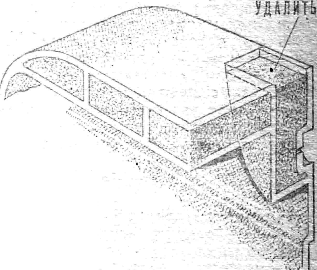
1 – marking the parting line, 2 – technological partition, 3 – half of a table tennis ball, 4 – nails at the point where the studs pass, 5 – foam washers.
Technological partitions can be cut out of plywood or hardboard using templates from a blank.
BOTTOM FORMING
Install one of the technological partitions in the bottom half of the matrix exactly along the parting lines and secure it with pieces of plasticine. Then polish both it and the matrix with parquet mastic and form the front and then the rear part of the sandwich structure hull. Reinforce the intermediate walls with two or three layers of fiberglass. After the resin has hardened, remove the technological partitions and glue the central section. The walls of the glued front and rear sections will serve as technological partitions during its formation. Cut the finished elements according to the markings and glue the lock “bath” along the perimeter of each section. After this, determine the position of the centerboard well along the central section and prepare a place for its installation. When gluing the stern section, do not forget to install the embedded part in the matrix, on which the fin seat is formed.
PASTING
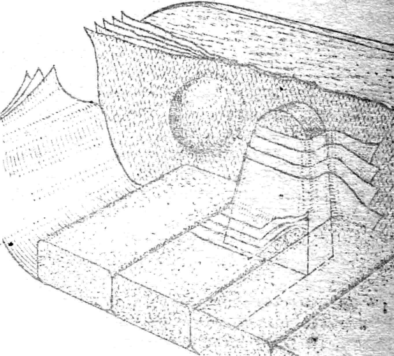
This work is more difficult than the previous one, since it is in the deck sections that niches will have to be formed to accommodate the joints of the sections. All three parts of the hull are connected by steel threaded studs passing through the central part of the board and round nuts located in niches of the stern and bow parts of the hull. To prevent mutual displacement of the sections in the plane of the joint, there are hemispherical protrusions (on the central section) and corresponding depressions (on the stern and bow sections) molded integrally with the hull parts. The same central hemispheres should also be on the additional section 1400 mm long, as well as niches for the nuts tightening the hull.
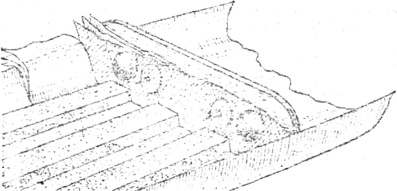
1 – bow section, 2 – center section, 3 – 1400 mm long section, 4 – stern section.
First, install the process partition in the matrix and secure it with plasticine. Glue foam washers of the same size as the rubber gasket to the process partition on its inner side. Also install two hemispheres on the partition — you can use a cut table tennis ball. Then form (in the same way as described in “M-K” No. 12 for 1980) the sandwich structure deck and the dividing wall. The latter must be reinforced near the tie rods with several layers of fiberglass. After that, install two foam blocks (their shape must match the configuration of the niche for the nut) and mold them with five to six layers of fiberglass. Do not forget to glue foam “noodles” — shavings approximately 3X15 mm in size — to the matrix and the process partition along the entire perimeter of the parting line. The mating part of the “lock” will be formed on it during the process of gluing the deck section. After the binder has hardened and the sections have been removed from the matrix, carefully cut the deck in the niche area and remove the foam.
Place the forward and aft sections back into the matrix, install the embedded parts on which the mast step and the upper part of the centerboard well are formed. Cover the sides of the matrix and the parting lines on the forward and aft sections with foam “noodles”, after which you can begin gluing the middle part of the deck.
When connecting each section, carefully adjust the end sections according to the template; it is most convenient to use a technological partition as the latter.
An additional section 1400 mm long (for tandem) is glued in the same matrix using the same technological methods, but it is necessary to provide niches for round nuts in the front and back. Drain plugs are installed on all sections of the body.
To give greater strength and tightness to the middle section, it is recommended to pass tie rods through the middle section along pipes formed from fiberglass on a paper mandrel and glued into the deck half of the middle section before assembly.
At this point the work can be considered finished. A dismountable sailboard with the same sail rigging as a monolithic one is used. The same can be said about tandem and tridem.
Y. ZOTOV, N. SHERSHAKOV
Recommend to read
 DOVETAIL — JIG SAW
To make the Board a groove type "dovetail" is not difficult. Two cut with a hacksaw, one blow chisels and groove ready. When processing the same chipboard or plywood such technology is...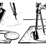 A COMPASS CUTTER
Carefully cut a circle from the cardboard using scissors is very difficult. To help in this work can usually tsyrkul fixed in his foot, as shown in the figure, a razor blade.
