 25 Nov 1933 soared gird-X — the first Soviet experimental rocket with LRE (liquid rocket engine). It was created in the Gird under the direction of S. P. Korolev on the project and calculations of Friedrich Arturovich Tsander.
Major theoretical problems of jet propulsion, the engineer-inventor of the F. A. Candera didn’t have to see your rocket in flight.
Enthusiast interplanetary missions, whose motto was “Forward to Mars!”, Friedrich Arturovich created his own school in the field of the theory and design of liquid jet engines. S. P. Korolev in the book “Rocket flight in stratosphere”, published in 1934, wrote of him: “Through his work over the last 10 years was the prototype of the first Soviet rocket engines”.
In the first brigade of Gird worked friendly creative team: A. I. Arctic, E. K. Moshkin, L. S. Dushkin, M. G. Vorob’ev, L. II. Kolbasina, and others. They, comrades and students of F. A. Tsander, completed the manufacture of rocket gird-X, and released her first flight.
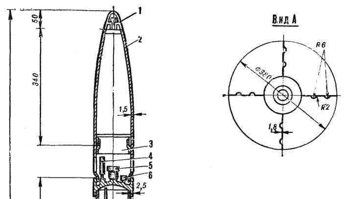
Rocket gird-X consists of a head fairing, instrument and motor compartments, tanks of oxygen and fuel, battery, pressure jet engine, the intermediate shells and rings, valves and fittings, tail.
Fairing is of two halves, it is the parachute. When the automatic device resets the cone, the parachute opens and the rocket gently lands.
The instrument compartment ka front wall of the oxygen tank is placed a safety valve, pressure gauge and fitting for the fill of oxygen.
Oxygen tank made of aluminum alloy, its walls form the body of the rocket. In the bottom of a tank welded fitting that is attached to the oxygen valve and the pipe passing through a tank of fuel to the manifold of a jet engine.

GIRD-X:
1 — scraper, 2 — fairing, 3 — instrument compartment, 4 — manometer 5 — safety valve, 6 — pipe for filling oxygen-7 — oxygen tank 8 — faucet oxygen, 9 — oxygen tubing, 10 — pressure accumulator, 11 — shell, 12 — valve and tee, 13 — a tank of fuel, 14 — regulator 15 — fuel valve, 16 — jet engine (No. 10), 17 — hull 18 — manifold.
The pressure accumulator (it is compressed to 150 ATM air) is a special balloon. It is connected to the pressure reducing valve and a tee from which two tubes: one having a shut-off valve in the oxygen tank, and the second is in the fuel tank. Due to the pressure of compressed air, liquid oxygen and fuel forced into the combustion chamber of the engine.
The compressed air is inside the shell, made of aluminum alloy.
The fuel tank has a bearing shell, which is also part of the rocket body. On the front wall of the tank with the fitting installed, from it to the combustion chamber is in the Pipeline. To the lower side welded lugs, to which the bolts are attached to tubular rod mounts the engine to the rocket. In the upper and lower walls of the tank welded tube, it passes through the tubing from the oxygen tank to the manifold of the combustion chamber.
Engine compartment made of sheet aluminium, rolled into a cylindrical shell, which smoothly into the tail fairing having a shape of a truncated cone. In this compartment are placed the jet engine, the pipelines of the oxidizer and fuel valve and fuel valve blocking the reverse movement of oxygen through the tubing. Tail fairing lower part is welded to the ring stiffness, which is screwed inside the compensating ring.
Jet engine No. 10. The inner walls of the combustion chamber and nozzle are made of heat resistant steel and outer of mild. Between the inner and outer walls there is a gap of 2-3 mm and in the area of the nozzles it comes to 4-10 mm. This gap is filled with liquid oxygen through the pipeline enters the annular manifold, and from there to the gap between the walls of the combustion chamber. Thus, the oxygen cools the combustion chamber, that is, takes away from her heat, and he heats up.
On the cylindrical part of the engine has openings located at an angle of 45° to the axis of the combustion chamber. Passing through them, the oxygen meets with the fuel flowing under pressure from the nozzle. Next, the pulverized fuel and oxidizer come in pear-shaped area of the combustion chamber where the spark plug ignites the mixture and, with the power escaping through the nozzle, pushing the rocket forward.
The tail Assembly consists of four stabilizers positioned at an angle of 90°. They are made from sheet aluminum alloy. Each stabilizer has two longitudinal grooves to give the structure rigidity.
Before launching the rocket gird-X was placed vertically in a special machine with a guide. Filled fuel and oxidizer, and then closed flood fittings and create the necessary working pressure in the pressure system. Then opened the taps, turned on the ignition, and the rocket accelerated rushed up.
BRIEF TECHNICAL CHARACTERISTICS
Dimensions, m:
length………………………………………..2,2
diameter…………………………………….0,14
Weight, kg:
starting………………………………….29,5
fuel……………………………………8,3
The engine thrust, kg………………………65-70
The motor is running, …………22
Payload, kg……………………….2
The calculated lift height, km…..5,5
E. MATYSIK, Brigadier collectors Gird


