
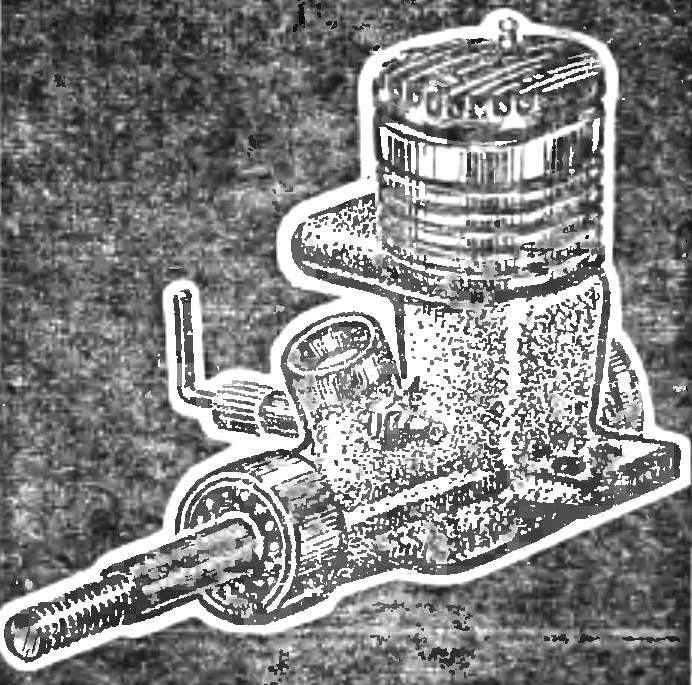
 In the hands of you new, smelling of castor oil Microdrive “meteor”. How many mysterious ceroplastes hidden under the surface of Carter. How to get the engine to open all my secrets and show what he’s capable of?
You probably know that before you put the engine on the model, it is necessary to spend its run. From her — from how the engine will live its first working hours, all depends on his fate, that they determine whether you “make friends” with his “Meteor” or “quarrel” with him.
So, the run-in.
Before starting the engine must be completely disassembled and thoroughly washed every detail with a mixture of gasoline with acetone or solvent № 646. This compound easily dissolves solidified upon storage engine castor oil. If necessary, grind the burrs and rough places. When disassembling each item tag, so that after Assembly it arose in its place. This is especially important for elements of the piston group: piston, pin and connecting rod. Note that the crankshaft in the bearings, and those, in turn — in socket installed easily (by hand).
Buying the engine, you need to pay attention to the condition of its piston. The surface of the piston visible through the exhaust window should be clean, without scratches and burrs, compression springy.
If necessary, using a paste GOI, diluted in kerosene, re-grinding the shaft to the bearings and bearings to the jacks. At the same time check the tightness of the spool and ease of rotation to wear Carter’s. Parts subjected to processing, rinse thoroughly in gasoline to remove residual abrasive paste.
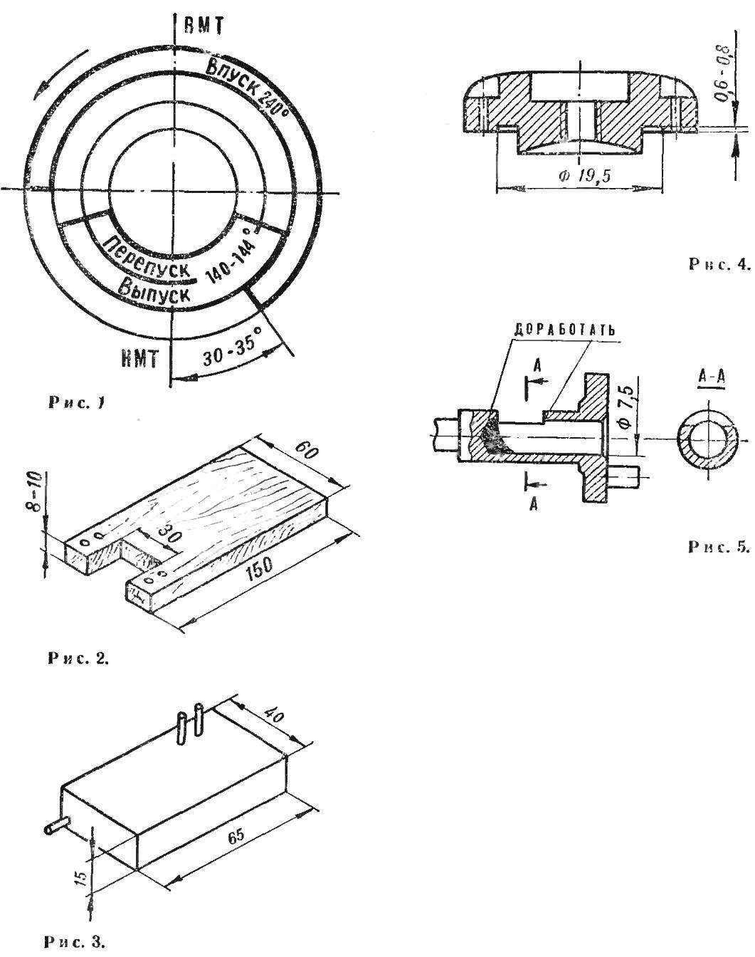
Then check that the actual valve timing of the phases specified in the factory passport. The last taken as a result of prolonged experimental work, and they need to follow when fine-tuning the engine. Figure 1 shows a diagram of valve timing with indication of limit deviations that do not affect engine power.
Verification is carried out. With the help of a degree disk (circular protractor) mounted on the crankshaft, slowly cranking the engine and locking the beginning and end of each phase (intake, output, and bypass), determine their actual values. If after the measurement phases it appears that they are beyond the value of tolerance, you must correct them.
Most often, deviations occur because of improper installation at the height of the sleeve relative to the housing. The position regulating linings by placing them under the flange or tortue boarding a plane liner in the crankcase. After this operation, install the cylinder head and carefully check its tightness.
It was the turn determine the degree of compression. It is controlled by the fill dose of liquid fuel or oil through the plug hole when the piston is at TDC (top dead center). Knowing the volume of the combustion chamber and using the following formula, calculate the geometric compression ratio:
E=(Vh+Vc)/Vc
where E is the compression ratio, Vh — working volume of the cylinder in cm3, Vc is the combustion chamber volume in cm3.
Running the engine spend at a low compression ratio equal to 6-7 (Vc =0,49 — 0,41 cm3 , respectively), in any case, it should not exceed the rated specified in the factory passport. Changing the gasket thickness under the cylinder head to achieve the required degree of compression.
The next step is to run the engine on the test bench. If not, you can use ordinary wooden “fork” (Fig. 2), made in the form of Carter. The engine is fastened with screws through the holes in the legs.
In any case, do not clamp the engine in a vise and clamps for Carter: he may be deformed, and this inevitably will bring the meteor down.
The tank (Fig. 3) for testing solder of tinplate. It should have two drainage and one feeding tube. The second drain pipe is used for filling the tank. Put it as close to the engine, positioning the upper surface of the tank for 5-10 mm above reklamnogo hole of the carb. Such installation of tank best meets the conditions of smooth adjustment and uniform fuel supply to the engine and eliminates overflow of the carb while preparing it for launch.
Standard diffuser Ø 6.5 mm carburetor to facilitate starting it is better to replace on a smaller Ø 3.5 — 4.0 mm. If not, you can half-section of staff of the diffuser to block neatly fitted wooden insert. Coming into the carb the air will pass into the gap formed by the insert and the nozzle part facing the diffuser. The spray hole of the nozzle should be turned to the airflow and some deployed down.
One more detail. For testing it is better to apply the screw (propeller) is larger than for normal operation. For engine 2.5 SME usually use the screw from pasikurowice of the motor or made it yourself. It can be of simplified construction because his task — the cooling of the engine.
First engine start-up to produce a special test fuel. Its recipe is given in each factory operating instructions. You can also recommend proven fuel of the following composition: methyl alcohol — 70%, castor oil — 30%.
When running the engine do not allow to develop high speed, which can be detrimental impact on his later life. To do this, adjust the carburetor to a rich mixture. Doing it this way. Running the engine to achieve stable operation. Then slowly turn needle jet — no more than one turn. This achieves the necessary high-speed operation of the engine: 1,000— 1,500 rpm less than the nominal. For engine MD-2.5 “meteor” when they run around 10-12 thousand rpm.
In head engine, installed the “cold” (with thick wire on spiral) candle. It will not allow to develop motor high rpm and prevent overheating. Sometimes it happens that from too rich mixture and low compression, not enough internal heat to keep the candle in the hot condition and the engine stalls. Then from the rectifier (or battery) through a resistor of 10-20 Ohm is connected in series to the spark down a small (for domestic candles 2-3) stress acting throughout the engine operation. Choose its value such that the exhaust through the window was clear faint dark-red heat of a candle.
After half an hour of work, you can regulate the flow of fuel to obtain the maximum possible speed to oblationem screw. After working for 2-3 min at full speed again pass on the “rich” mixture. In the next half-hour this procedure was repeated 2-3 times. After conducting the trial run on the engine to install the propeller with smaller diameter and pitch than the roller, and conduct experiments for the selection of the optimum compression ratio.
The complex preparatory and staging of works allows for a compression ratio of 9-10 and on standard fuel without additives to 0.5 HP with an 18.5—19 thousand rpm. the engine must be installed in the diffuser with a diameter of not less than 6.5 mm, and it is desirable to use a candle with a spiral of platinumiridium alloy.
For higher power you need to perform additional work. Revision are:
CYLINDER HEAD. The lower sealing plane pruned to a height of 0.6—0.8 mm (Fig. 4). This gives you the opportunity to increase the compression ratio to 10-12.
CRANKSHAFT. The inner surface of the inlet channel is first treated with a large sandpaper and then fine. The processing done when the inner surface will not remain transverse scratches from the factory of the drill channel. To protect the rod journal from damage during processing you put on the vinyl chloride tube of appropriate diameter.
Besides, it is necessary due to the melting of the soft solder (tin) and blunt edges, as shown in figure 5, to improve the transition from the inlet ports to the channel. It gives tangible effect when the engine is running at high speed (15-20 thousand rpm)
PISTON GROUP. It should be easier without the need to achieve a record of small mass parts. The best modern engines the piston weighs 5,9—5.2 g, the connecting rod is 2.0 — 1.7 g, the finger — 0,9—0,8 g. Excessive relief can cause damage to the engine from a thermodynamic and mechanical overloads during operation.
Removing the metal part from the inner surface of the piston, try not to reduce the landing length of the holes in the lugs and the thickness of the bottom. This work is best done “finger” dental cutter installed in the Chuck sleeve of the drill. Good results can be achieved, removing a thin shaving sharp triangular scraper.
The minimum cross-section of the body of the connecting rod when the relief shall not be less than 5X2 mm. The transition of the upper and lower heads to the web, make smooth “podraza” radius 1-1. 5 mm. Special attention is paid to the size and cleanliness of processing of oil holes in the heads, depends on uninterrupted supply of oil to the heavily loaded working surfaces of the connecting rod neck and piston pin. The thickness of the heads is left unchanged, the entire surface of the polished rod with GOI paste, and then thoroughly washed in kerosene.
(To be continued)
R. OGARKOV
Recommend to read
 SIMPLE STEREO AMPLIFIER
The use now many are addicted. Almost PI one radioactive not complete without high quality playback equipment. And the shelves are not empty radiomatinal: the attention of buyers offered...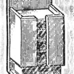 MATCHBOX “ELEVATOR”
Matches... How many times we use them for the day! To do this, constantly having to open and close the drawer or get them off the shelf — they are thrown on the table — the baby was right...
