“AIRCRAFT” OPTION

Anyone who has ever seen race speed RC boat, certainly will remember the “aerobatics” microcameras that they performed by teams of “pilots”.Requirements for such models. Without their accurate implementation is impossible to create a modern first-class equipment. To a large extent propulsion and manoeuvring properties of microcameras depend, in particular, of the total weight of the structure. Significant share of it is the weight of the body. A good solution to build the lightest boat without the use of a short supply of balsa with a minimum of fiberglass and epoxy resin, is proposed and successfully implemented the master of sports Vyacheslav Baryshevym. Speaking out of the competition at the open championship of Moldova, he was far ahead of its rivals.
Housing microcamera, designed on the basis of aircraft load-bearing sandwich monokoko, has a number of advantages even before the widespread modern Celestica – or carbon-fiber. It has high rigidity and that is extremely important for advanced well suppresses noise. The technology of its vyklicky is so versatile that allows you to create the same case for boats with internal combustion engines (class rbns) and for models with electric motors (class of BSE). But for the last is especially important every gram of weight saving — the lighter design, the more batteries will be able to place on the Board, and the faster it will run microcode.
 
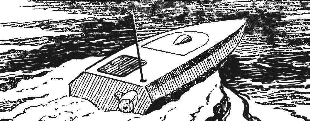
RC sudomodel with the engine working volume of 2.5 cm3
RC sudomodel with the engine working volume of 2.5 cm3:
1 — front frame. 2 — channel muffler, 3 — intake and Suha 4 — bow frame. 5 — deadwood, 6 — Klondike solitaire mounting deadwood. 7 — tube d 3 mm water intake for engine cooling. 8 — point output Bal-
Lera, 9 — the mounting bracket of the muffler 10 to cover radio equipment 11 — battery 12 — servos, 13 — priemniy, 14 — fuel tank 15 — engine compartment lid, 16 — tube water outlet engine coolant. The muffler and the propeller is conventionally not shown.

 
The manufacturing technology of the hull resembles a conventional method of forming the matrix. Carefully perform the blank on the exact contours of the future microcamera, removed from it a fiberglass “mold” is a matrix where after finishing the preparatory and finishing works and wikiepedia case.
 
Proektsiya
Proektsiya “Body”
 
The work begins with coating the surface of matrix thin separating layer, then applied a layer of epoxy resin, pigmented artist oil paints. The introduction of oil paint is useful for the plasticization of the resin and allows to obtain a painted casing, resistant to fuel components and to mechanical damage. To the not yet hardened layer must be lapped annealed fiberglass 0.2 mm thickness, pre-impregnated with the same binder composition.
 
The following operation: display the foam layer thickness 3 mm. Material — sliced foam brand PVC-1 or PUF. Pre-prepared sheets are adjusted to each other even in the dry matrix. After laying the foam on fiberglass Vileika free surface coat epoxy and privorovyvat internal power trim — also of pre-impregnated fiberglass with a thickness of 0.2—0.3 mm.
 
Reducer power plant
Gear power plant:
1 — handwheel, 2 — cone, 3 — pinion (steel) 4 — rear cone, 5 — bow engine bearing, 6 — toed engine, 7 — crankshaft, 8 — nut 9 — washer, 10 — driven gear 11, the lower cone, 12 — gear case, 13 — spacer tube, 14 — ball-bearing 7X17, 15 — details of joint of the propeller shaft.

 
To hold the “sandwich” in the compressed state until curing of the binder and to avoid air bubbles and nepolean, the matrix with the housing immediately after molding was placed in a sealed plastic bag, the open edge of which is carefully tied around the hose. It is connected with a vacuum pump, from the “packaging” sucked the air. In the vacuum Vileika aged to fully cure the resin. It is better to be safe and to allow the pump to work for another few hours.
 
In conclusion, both parts of the housing cut along the contour and adjust to each other.
 
Fuel filler
The neck of the fuel tank:
1 — cap (bottle cap), 2 — collar (brass), 3 — nut 4 — nozzle, 5 — elastic coupling (silicone tube), 6 — standpipe (brass tube d 4 mm), 7 — cargo (steel).

 
In the bottom part of the glued frames made on the same principle (fiberglass — foam plastic — fiberglass). The transom and rear bulkhead are prepared holes into which sealed tubular fiberglass channel under the muffler. Cover matousek (cut portion the upper housing portion) is hung on the hinges. It locks in the closed position and glued a small magnet, a “sticky” to the strip of metal on the deck. This “castle” is quite reliable.
 
After assembling and adjusting all the “stuffing” RC the two housing parts are connected on the resin with a gasket around the perimeter seam of the harness fiberglass cloth impregnated with the same epoxy.
 
Fixing unit motor
The clamping motor:
1 — panel,2 — bearing (a mixture of chopped fiberglass and epoxy resin). 3 — nut, 4 — motor,5 — rubber washer 6 — sleeve (rubber tube) 7 — M4 screw,8 — sleeve.


Power plant model — a modified engine MVVS 2,5 cm3. Regular pair of piston — cylinder replaced by “color” from the domestic engine CSTOM. Head were altered — was split, with vyfrezerovkami a channel for the passage of cooling water flow. The carb is from a nitro “Very is 6.5”.
 
Single-stage reducer with cylindrical gear has meiose-rises a distance equal to 24 mm, module of gear teeth — 0.8 mm, gear ratio 1 : 1,5.
 
The power plant is mounted on the housing at four points. The M4 screws, held together with reinforcing roller-
coy patterned through the rubber dampers, between the washers and clamped the motor mount. Return the nuts embedded in the body with a mixture of chopped fiberglass and epoxy resin. Washer shock absorbers — from a sheet of porous rubber with a thickness of 5 mm, when assembled, they are compressed to 3 mm.
 
The muffler is supported in the rear by a clamp fastened on the corner of the transom. From contact with the walls of the channel it protects the tape heat-resistant rubber. When you install the muffler it is necessary to consider that the gap between it and the fiberglass channel must not be blocked — the only exit of the cooling air.
 
The silencer
Muffler.
 
The tank is rectangular in shape with a volume of 150 cm3 soldered tin with a thickness of 0.3 mm. It is fitted with soldered legs. At the top front of the soldered fitting boost, it connects to the muffler by a tube of heat-resistant rubber.
 
Aft of the bottoms securely mounted gelmanova pipe. Its mounting pay particular attention during racing when you pile on the buoy — its share may drop significant loads. The stock of steel wire d of 3 mm by spot welding is welded to the rudder, cut from stainless steel with a thickness of 1 mm.
 
Propeller shaft of steel, 4 mm. d Deadwood — tube stainless steel d XI 6X mm, it is soldered brass solitaire with a thickness of 1 mm. Bronze bearings of the propeller shaft are incorporated in the ends of the deadwood. Prop 0 35 mm, steel, geometry close to the propellers “X”series.
 
V. BARYSHEV

Recommend to read

  • THE DECISION PROMPTED GLIDERTHE DECISION PROMPTED GLIDER
    Journal with drawings of Cordoba aerolizer who have developed a record speed, took all the guys from our club. "We will build these!" — without hesitation, they said. To dissuade the...
  • REKORDSMENKA CHARACTERREKORDSMENKA CHARACTER
    In the fall of 1978 with a group of rocketmodeler I was going to leave for a training camp in the Crimea. Literally the day before our departure from there to Central aeromodelling club...