AIR BENDS

AIR TURNS

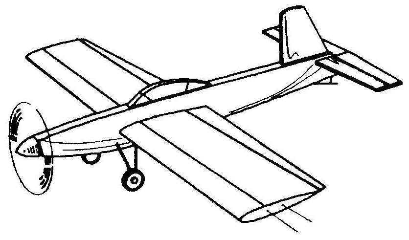
Young conovici-only pilots rarely taken for the creation of highly complex models. Basically they design a simple and feasible model of universal definition, which are equally suitable for testing of flight control avionics complex, and for competitions. We must remember that half of success on the performances of only pilots — the run-in, reliable motor. More suited KMD-2,5 and MDS-MDS or a 3.5-4 in export performance. It is simple, technological and, most importantly, “volatile” model — is proposed for the attention of young korovikov. Pilotage designed based on the available materials instead of lime for many parts, you can use high quality blanks from aspen, alder or poplar.
Manufacturer model starts with the forward fuselage. It is important to accurately lay out and have a good handle niche engine mounts and holes for the power elements of the wing — spars and the shelf front edge. The surface of the motor facing inside the circle, enhanced by a shaped plate made of plywood with thickness 1,2 …1,5 mm. Under foot the engine mounts glued beech blocks, the shape and dimensions of which provide Vegas the axis of the engine and the clearance between the bottom of the sump and the plywood lining. For mounting the engine in the prepared holes are inserted epoxy resin or four hairpin MZ. Beam of the fuselage is formed with the edging strips and plates from the packing foam, docked to the bow. In the tail section is glued the lug with the cutout for the stabilizer. The assembled fuselage is cleaned with fine sandpaper and fitted by a thin writing paper on diluted with water (ratio 1:1) PVA glue. In this paper consistently rolled up to the plane of the Board from nose to tail. The overlap of paper on the wooden part of the fuselage — no more than 7…10 mm. Drying the paper should be uniform, otherwise the beam will be warped.
 
The next stage is Assembly of the wing. It has a classic case diagram that provides a lightweight design and familiar to many assemblage. Ribs and noses are cut from 1 mm plywood or 2 mm veneer, processing them is in the pack. On finished parts to reduce weight provided openings.
The workpiece shelves of the spar and edges are cut from high quality grained pine or spruce. The tip is made from 2.5…3 mm plywood. The transition from the ending to the edges of the reinforced corners of the I-mm plywood. Guides output cord of the ending pieces of tubes or springs of the seal is pasted at a distance of 60 and 80 mm from the leading edge. The external console at the ending between the side members is secured a weight 20…25 g. Between the shelves of the spar — root six bays, which are sutured 1 mm plywood or veneered — wall of the spar. The direction of the wood grain is vertical. Rocking control manufactured of duralumin sheet thickness of 2 mm, and the holes for traction riveted copper caps (tube 3×1 mm). The axis of rocking — steel, with a diameter of 2.5…3 mm. Node rockers mounted between the flanges of the spar by the first nozzle rib outer wing. At the roots of the consoles on the top and bottom are fixed strips of plywood or veneer, bent over the candle on the profile of the wing (to them afterwards attached plating). Thrust cord self — made steel wires woven of two wires of diameter 0.3 mm. rod to the flaps and the Elevator hewed out Reiki 6×6 mm, it Satelitni part is made of 2-mm needles.
 
Control horns on the flaps and the Elevator applied brand or made from plastic box area of the engine. Loop mount the rudders — tin with the axis of the paperclip.
 
General view of the cord aerobatic models
 
 
General view of the cord aerobatic models.
 
 
The fuselage
 
Fuselage:
1 —the forward part (Linden, plate, s8), 2 — top edging (pine, rack 8×3, L650), 3 — a filler for the wing (foam packing, sheet, s8), 4 — brace (lime, block 8×6), 5 filler tail (foam packing, sheet, s8), 6 — brace the tail (pine, rack 8×3), 7 — tail boss (Linden, plate, s8), 8 — lower trim (pine, rack 8×3, L650), 9 — plate motor (plywood, s1,5), 10 — patch block motor.


Horizontal tail
 
Horizontal tail:
1 —the ending of the stabilizer (lime rack 6×3) 2 the leading edge of the stabilizer (pine, rake (6×3), filler (packing foam sheet. s6). 4 – the trailing edge of the stabilizer (pine, rack 6×4) 5 – insert under the pig (pine, rack 6×4). 6 – the leading edge of the Elevator (pine rack 6×3), 7 – trailing edge rudder (pine, rail 6×2). 8 – ending the helm (lime, rake 6×3).


Control scheme
 
A control scheme.
 
 
Fuel tank
 
A tank of fuel.


An airfoil with a flap
 
Wing profile with flaps.
 
The wing and the strut units of chassis for models of competitive type
 
The wing and the strut units of chassis for models of competitive type:
1 – front (steel wire with a diameter W). 2 screws”screws, 3 -wheel, 4 – spacer (tin plated. s0,3). 5 -the mount (duralumin, sheet. s2). 6— installation tool tray (beech. bar 10×12, L100).


The fuselage and the strut units of chassis for the model training of the type
 
Fuselage and strut units of chassis for the model training of the type:
1 — fuselage 2 — the mount (aluminum, sheet, s2), 3 — screws”tapping screws”, 4 — front (steel wire diameter 3) 5 — wheel 6 — spacer (tin plated, s0,3).

 
Ready console upholstered Mylar film thickness of 25 microns. Sheathing attached with glue type BF or “Moment” warming up joints with hot iron. The fuselage and wingtips are covered with three coats of liquid nitro lacquer, and seams of sheathing — one layer of the fuselage can be painted with colored enamels toplivostojkaja.
Tail and flaps made of foam and surrounded by wooden edges. On their surfaces are fixed strips of wide tape-“Scotch” on the pet basis. The edges of the tape on the edges lapped and bent “baked” with a Flatiron heated to 100° C. the Finished parts usually not painted — Scotch gives them a beautiful appearance. The flaps and Elevator are mounted on the wing and the stabilizer using the hinges. On the moving elements are fixed control horns and linkages. In the tail part of the fuselage is glued to the stabilizer.
 
The fuel tank soldered from a tin-plated sheet under the “pot”. On the fuselage it is attached ears made of wire or rubber thread. Skid is made from steel wire with a diameter of 1.2 mm. the Engine is mounted without the propeller, then checks the alignment of the model, the optimal position should be 25. ..28% of SAH from the leading edge of the wing. Based on the real situation of the COG, select the place of installation of a decorative canopy and fin. In exactly the same way as the keel is the horizontal tail and the arc of the canopy is bent out of aluminum knitting needles with a diameter of 2.5 mm. At its ends secured to the plywood gusset plate, place the arc wrapped thread. The size and location of the cabin is changed, the selection of the alignment.
 
Chassis model — torsion type. The wing strut is bent from spring steel wire with a diameter of 3 mm. they are Fastened to the beech planks with longitudinal grooves of a cross section of 3×3 mm, mounted in the consoles of the wing. Another option is to install struts to the fuselage before the wing. In any case, it uses proprietary wheels with a diameter of 45…50 mm. On the racks they are fixed in a sealed tin washers. If the model is run on a grassy platform, the chassis mounting optional. The recommended propeller diameter and pitch 220 120…130 mm.
 
ERMOLAEV candidate master of sports

Recommend to read

  • FLOATING LOUNGERFLOATING LOUNGER
    It is hardly necessary to prove to anyone, what are the benefits to human health water swimming is much greater than even all the recognized Jogging. But while running, when you get...
  • TANKS FOR SELF DEFENSETANKS FOR SELF DEFENSE
    The self-defense forces — the so officially called armed forces of modern Japan. In accordance with the Potsdam Declaration in 1945, the Japanese army was disarmed and demobilized. 30...