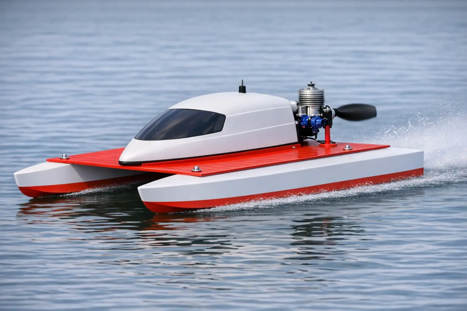
Building and tuning an airboat hydroglider is much easier (and cheaper) than building a racing boat model with a propeller, gearbox, and liquid-cooled engine. At the same time, if properly designed, it is practically not inferior to the “classic” setup in either speed or maneuverability.
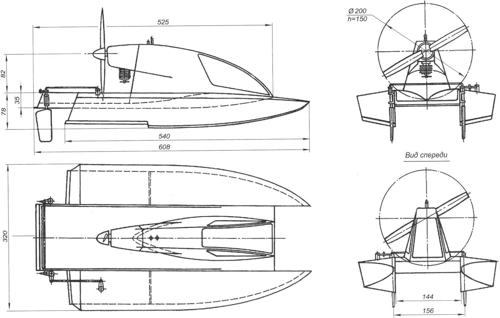
The proposed radio-controlled model with an air propulsor is based on a tunnel-hydroglider hull. It consists of four major units: a pair of side floats, a central bridge section, and a cabin with the powerplant.
The floats have a traditional framed structure with 3 mm plywood bulkheads and 4×4 mm pine stringers. Deck, bottom, and side skin are made of 1 mm plywood, while the internal load-bearing side panel is made of 3 mm plywood. The floats are assembled on flat structural side panels. All bulkheads are butt-glued to them with epoxy, then connected by stringers. The finished frame is faired, and skin panels are then glued sequentially (bottom, side, deck). Before that, joints between the bottom and sides are filled with liquid epoxy adhesive to ensure watertightness. It is also useful to treat the inner float surfaces with the same binder to improve wood water resistance. A sealed hatch is arranged at the rear of each float: in the right one for the steering servo, in the left one for the radio receiver.
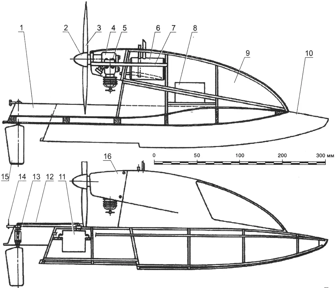
1 – bridge section; 2 – prop spinner; 3 – air propeller (Ø200 mm); 4 – engine; 5 – engine mount (4 set plates); 6 – tank; 7 – engine bed; 8 – battery pack; 9 – cabin; 10 – float; 11 – steering servo; 12, 14 – control rods; 13 – steering bracket (duralumin, sheet s2 mm); 15 – rudder blade; 16 – engine cowling
The central bridge section is also a built-up structure. It consists of right and left side panels (each is glued from two plywood parts), pine crossmembers, and 1 mm plywood skin. The key point here is watertightness, so after the bottom is glued on, the seams are filled with liquid epoxy adhesive. When making the bridge section, drainage holes should be provided in the crossmembers, and a hole with a plastic plug should be made at the rear. If water still gets inside, it can be drained through these openings.
The model cabin is assembled from plywood (3 mm) bulkheads, pine stringers, and 1 mm plywood skin. In the rear part of the cabin, an engine bed is glued in, consisting of two symmetrical 8 mm plywood parts. In the central part of the cabin, a plywood platform is fixed between bulkheads to mount the battery pack for powering the radio equipment. A 75 ml fuel tank is installed in the rear cabin compartment.
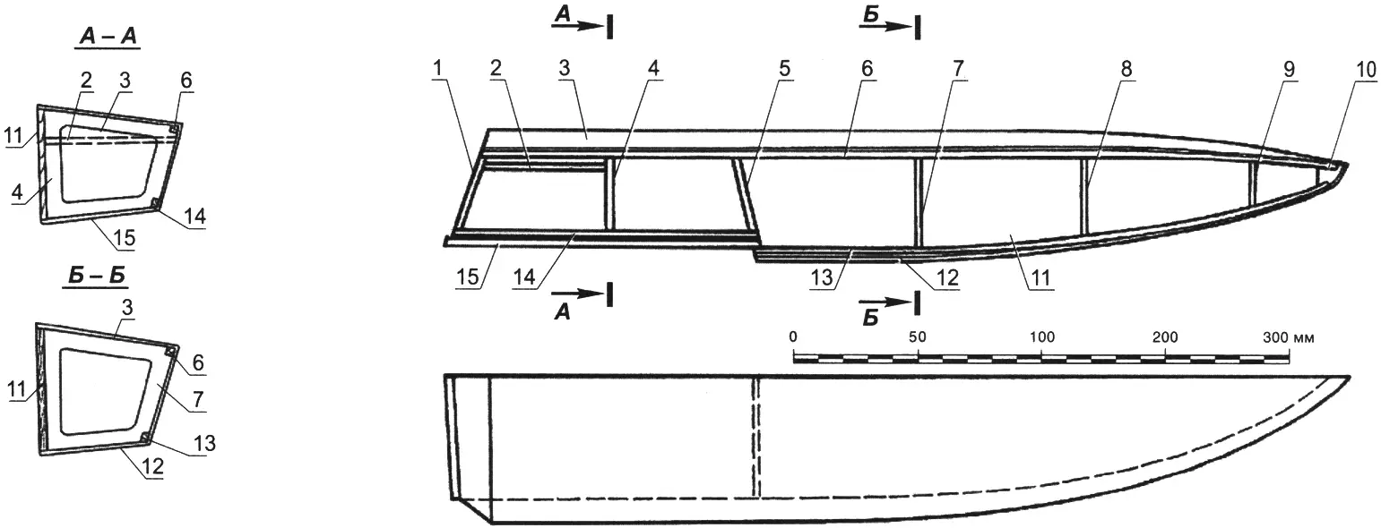
1 – transom board (plywood s3 mm); 2 – steering servo mounting platform (plywood s3 mm); 3 – deck skin (plywood s1 mm); 4, 5, 7, 8, 9 – bulkheads (plywood s3 mm); 6 – side stringer (pine, batten 4×4 mm); 10 – bow block (linden); 11 – structural wall (plywood s3 mm); 12 – bottom skin (plywood s1 mm); 13 – chine stringer (pine, batten 4×4 mm); 14 – rear chine stringer (pine, batten 4×4 mm); 15 – skin of the stepped bottom section (plywood s1 mm)
Model assembly requires care but is not especially difficult. Floats aligned on a flat jig board are glued to the central bridge section with epoxy resin, and the cabin is mounted on the bridge. Installation is done in two stages: first, 4×4 mm pine battens are fixed on the bridge and bent according to the cabin-to-bridge joint line; then the cabin itself is glued to them.
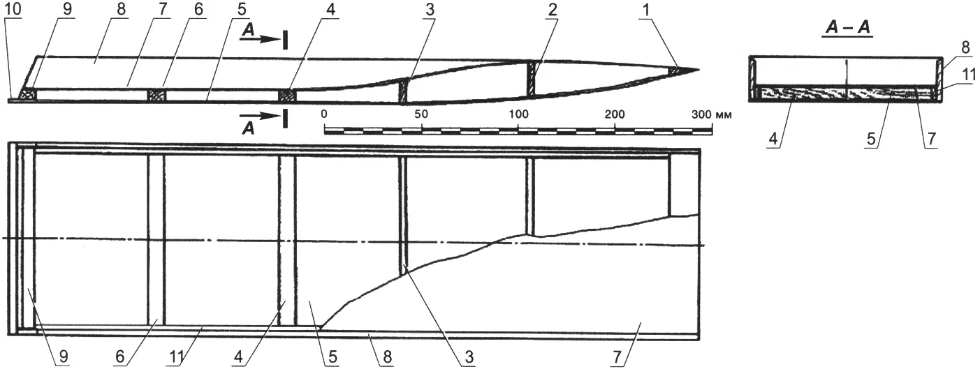
1 – bow block (pine); 2, 3 – front crossmembers (plywood s4 mm); 4, 6, 9 – rear crossmembers (pine, batten 15×15 mm); 5 – bottom skin (plywood s1 mm); 7 – deck skin (plywood s1 mm);
8 – outer side plate (plywood s4 mm); 10 – stern spray rail; 11 – inner side plate (plywood s4 mm)
The model dimensions allow installing engines with displacement up to 2.5 cm3. For these engines, an air propeller of 200 mm diameter and 150 mm pitch is suitable — a mirrored copy of a standard nylon propeller. To compensate for rotational torque, the engine axis should be shifted to the left (top view) by about two degrees. To increase longitudinal stability, the propeller axis should also be tilted upward by the same two degrees (side view). These values should be fine-tuned based on test runs. With the engine installed correctly and steering in neutral, the hydroglider should move strictly in a straight line. The engine is covered with a cowling made from 1 mm AMg or AMts sheet.
A twin-blade rudder unit is mounted on the bridge section, consisting of a pair of U-shaped rudder brackets (duralumin) and two rudder blades. The blades are assembled from a Ø3 mm steel rudder shaft and a plywood plate with a symmetrical lenticular profile. The shaft is glued into a drilled hole in the rudder blade. The right and left rudders are linked by levers and a transverse rod, forming a setup similar to an automotive steering linkage.
“Modelist-Konstruktor” No. 6’2025, Igor TEREKHOV
Recommend to read
 ON THE TRACK THE AIRBOAT
Popularity RC boat is steadily growing, especially among beginners are aerolister as to design, fabricate, and debug a model is easier than racing sudomodel with the propeller,... “COMPACT -800” MOTOR FOR ALS
Numerous rallies of Amateur aircraft collected hundreds of enthusiasts, small aircraft, and it clearly showed that the interest in the design of Amateur aircraft huge. However, in...
