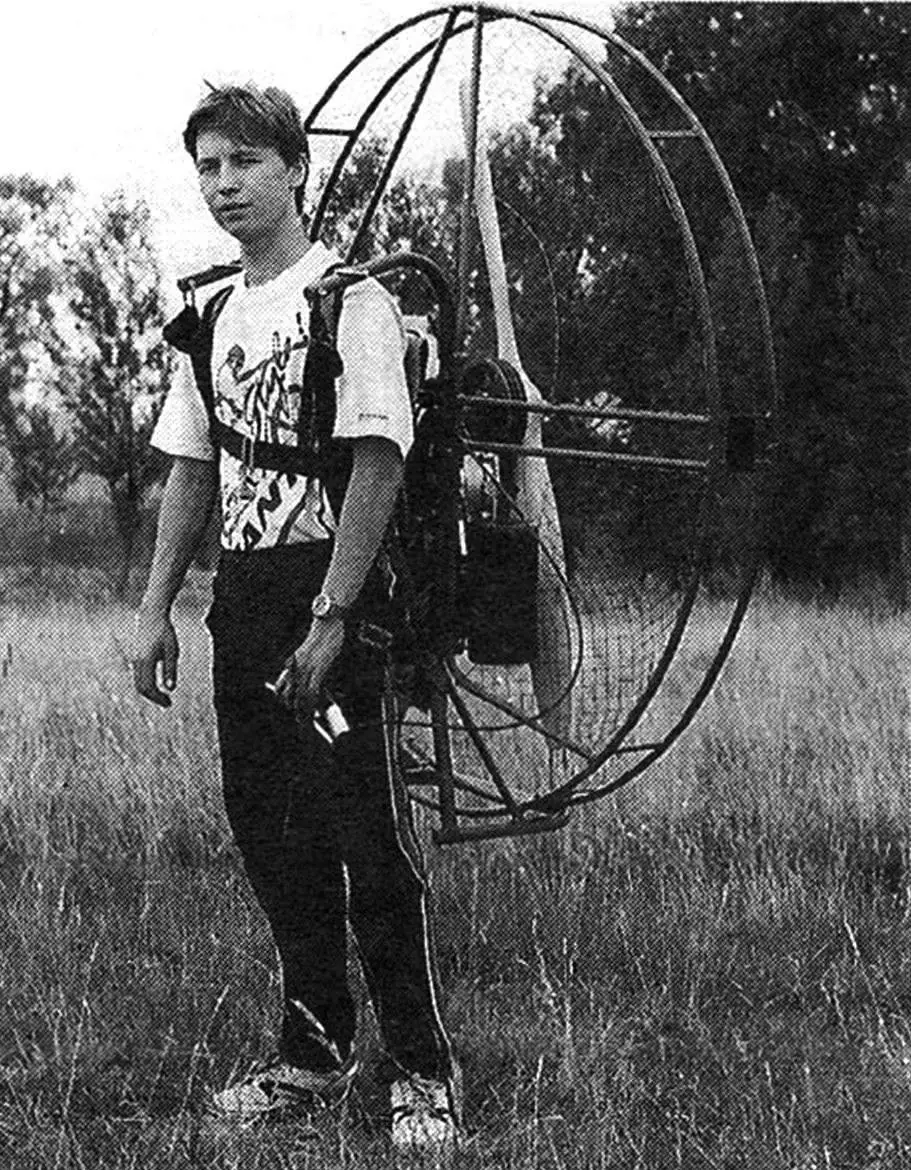
In the late 1980s, the family of light vehicles with mechanical engines (from motorcycles and snowmobiles to ultralight aircraft) was joined by a new type of ultralight aircraft, which received the official (according to FAI classification) name of powered paraglider. However, in colloquial speech it is often called a paramotor (PM), meaning the entire apparatus. The word itself originated from the trademark of one of the European companies.
Structurally, a paramotor is an autonomous unit with an internal combustion engine and an air propeller in a protective guard, with a built-in fuel system, having a device for starting and controlling the engine.
Functionally, it is a power plant for a paraglider that allows it to take off from a horizontal, more or less level area without using air currents.
The unique properties of PMs — low flight speed, ease of control, undemanding to takeoff and landing areas, the lowest noise level among all powered aircraft — are best revealed during air walks in good weather. In this regard, recent years in Europe have seen a real paramotor boom. To a much lesser extent (due to the high cost of foreign units: $6-16 thousand per set), but nevertheless noticeably, interest in PMs is also manifesting in the post-Soviet space.
Our team, which united ultralight aircraft enthusiasts and was later named “Arey”, took up PMs in 1992. The first experimental prototype was tested a year later, but despite the huge amount of refinement work, its flight and operational characteristics turned out to be completely unsuitable. It was followed by a series of two units with already improved performance, but with consumer properties that still did not satisfy us. However, already in 1994, this work was awarded a diploma at the All-Russian Ultralight Aircraft Festival.
The first PM with acceptable consumer properties was built in 1995 under the name “TATUSH 1.2”. Its improvement continued, and after a series of serious modifications, the new version received the name “TATUSH 120”. Thus, it took four years and several unsuccessful prototypes to make a good paramotor! And those homebuilders who expect to build something on the first try that will immediately fly, drive, and swim can only be sympathized with.
“TATUSH 120” is the third generation of paramotors, the main parameters of which were determined when creating the experimental prototype. Technical characteristics and properties allow it to be successfully used for recreational flights. It is also well suited for competitions and flight training.
| PARAMETER | TATUSH 120 | TATUSH 210 | TATUSH 300 |
|---|---|---|---|
| Engine | A-170 | SOLO 210 | HIRTH F33 |
| Power, hp | 15 | 16 | 22 |
| Propeller diameter, m | 1.2 | 1.2 | 1.24 |
| Static thrust, kg | 46 | 50 | 70 |
| Dry weight, kg | 26 | 21 | 30 |
| Crew, persons | 1 | 1 | 1—2 |
| Payload, kg | 100 | 100 | 150 |
| Fuel capacity, L | 5 | 5—10 | 5—10 |
| Rate of climb, m/s | 1—2 | 1—2.5 | 1—4 |
| Ceiling, m | 3000 | 3000 | 5000 |
The defining feature of the series is the air propeller diameter — 1.2 m. Using a propeller of such a large size increases the thrust-to-weight ratio of the unit (at the same engine power), which allows significantly reducing the takeoff run and increasing the rate of climb. And thanks to the fact that at cruise mode the engine operates at lower power, its noise and fuel consumption are reduced, and service life is increased. This diameter is optimal for multi-purpose paramotors. Further increase in propeller size gives only a small increase in thrust, but its guard begins to interfere with the paraglider canopy inflation, and weight and torque increase. Apparently, 1.3 m is a reasonable limit for the propeller. Paramotors with a smaller diameter are also not very promising: an experimental prototype with a 1 m propeller found no application, as a 1 kg weight reduction did not compensate for a 5 kg drop in thrust and an increase in noise level.
The parameters of “TATUSH 120” correspond to the most popular foreign PMs. As a rule, this is a single-seat unit weighing 18 — 25 kg with a two-stroke single-cylinder air-cooled engine with a power of 15 — 18 hp, a belt reducer, a fuel capacity of 5 — 10 L, and a propeller with a diameter of 1 — 1.3 m. Such a paramotor develops a static thrust of 40 — 60 kg and is oriented toward recreational flights of pilots weighing 60-100 kg.

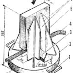
1 — removable arches (AMg6, tube 26×2), 2 — section of dismountable air propeller guard (AMg6, tube 12×1), 3 — tie-down straps (LTK-44-1600 tape, Velcro-type fastener), 4 — muffler, 5 — frame, 6 — engine, 7 — carburetor, 8 — fuel tank (canister), 9 — carabiners for attaching paraglider lines and pilot’s harness system, 10 — air propeller, 11 — pilot’s harness system, 12 — engine control handle (RUD), 13 — safety loop (LTKP-26-600 tape), 14 — engine mounting studs, 15 — bracket (steel 45, angle 50x50x5), 16 — shock absorber, 17 — M8 bolt, 18 — M6 bolt, 19 — fuel tank basket (D16T, strip 20×2), 20 — removable arch and guard retainer (Kh18N9T, rod Ø5), 21 — spring ring, 22 — fishing line.
The unified engine subframe and guard allow installation of different types of engines on the paramotor, which makes it possible to create a range of units of similar purpose but with characteristics that best meet the needs of specific pilots. Currently, the main engine is the A-170 (power — 15 hp, weight — 13.3 kg). A variant with the widely used SOLO 210 engine (18 hp, 10.2 kg) has also performed well.
We would not have made good paramotors without solving the engine problem — there was no suitable domestic engine, and there still isn’t. The only real solution was to make our own. But if we were to design and build such an engine from scratch, the associated problems would kill the venture. Therefore, in the A-170, only the crankcase and ignition housing are completely original. The cylinder-piston group with some boosting and the crankshaft are borrowed from the “IZH-Yu-5” motorcycle. The advantages of “Jupiter” parts include high and stable manufacturing quality, as well as relatively low cost and wide availability. Disadvantages — relatively large weight for such displacement, reduced cooling efficiency of the cylinder head due to the ribs being positioned across the crankshaft axis, and the most important drawback for serial production — the “pairing” of these parts. As a result, on half of our paramotors the muffler is located on the right, the tank and carburetor on the left, and on the other half it’s the opposite. The pull starter and electronic ignition are from the “URAL” chainsaw. All purchased parts used in the engine undergo inspection for compliance with increased requirements for a highly loaded aviation engine.
Currently, the engine is fully developed. It can be installed on any vehicle with an air propeller. Despite unremarkable specific parameters, in terms of overall performance it is simply excellent. Nevertheless, its base model is constantly being improved, and various equipment options are appearing. The design allows both direct installation of the propeller on the crankshaft and the use of reducers with various gear ratios.
The engine is attached to the paramotor frame on three shock absorbers made in the form of rubber-metal bushings. A well-matched engine mounting scheme and shock absorber stiffness allow complete elimination of vibration transmission from the engine to the pilot.

1 — partition (s1), 2 — outlet pipe (tube 20×1), 3 — housing (sheet s1), 4 — inlet pipe (tube 48×5), 5 — flange (sheet s4).
To reduce the engine noise level, an effective two-chamber muffler is used, installed directly on the exhaust pipe. This outwardly simple element is subjected to large thermal and vibration loads, and its design and manufacturing technology required careful debugging. Due to their small weight and dimensions, mufflers of this type are installed on most foreign paramotors. But there are already several models with tuned exhaust systems that significantly improve the power and economic performance of two-stroke engines. The same system is planned to be used on a prospective model, as its first experimental prototype increased static thrust by 2 kg and significantly reduced noise.

1 — air propeller, 2 — washer (Kh18N9T, sheet s1.5), 3 — M8x20 bolt, 4 — spacer bushing (steel 45), 5 — bearing 180204 (2 pcs.), 6 — M8x70 bolt (4 pcs.), 7,13,15 — Grover washers, 8 — driven pulley, 9 — belt 0-670, 10 — drive pulley, 11 — split cone (steel 45), 12 — washer, 14 — M10x20 bolt, 16 — M8x55 bolt (4 pcs.), 17 — bracket, 18,19 — M8x35 bolt and Grover washer, 20 — air propeller shaft, 21 — engine shaft, 22 — engine housing.
A large-diameter propeller requires a reduction in rotational speed. For this, most foreign companies use a reducer with a poly-V belt, which has high efficiency and service life, but is expensive and requires very high accuracy and cleanliness in pulley manufacturing. The A-170 is equipped with a traditional 3-groove V-belt reducer with domestic belts. A gear ratio of 1:2.5 is optimal for matching a 1.2 m diameter propeller with an engine developing maximum power at 6 — 7 thousand rpm, ensuring a blade tip speed of no more than 170 m/s, and at cruise mode — 100 — 120 m/s. The influence of this parameter on the noise level created by the paramotor is great. Thus, the already mentioned paramotor with a one-meter propeller, a gear ratio of 1:1.7, and the same engine turned out to be noisier precisely because of the high peripheral speed and specific load on the swept area.
On “TATUSH 120”, the tank is installed to the side of the engine directly above the carburetor, and fuel is supplied by gravity, which made it possible to abandon the expensive unreliable fuel pump and priming bulb, reducing weight as a result. The fire hazard of the gravity feed scheme (by the way, widely used abroad) is greatly exaggerated, as no engine part heats up to the ignition temperature of gasoline (630°C). In addition, this tank location allows monitoring fuel quantity in flight (a great rarity for paramotors), and the built-in valve allows removing it when transporting the PM and adjusting the carburetor without draining fuel (which is gasoline with an octane number of at least 91 mixed with SUPER-2T category oil in a 50:1 ratio).

1 — engine, 2 — driven pulley bracket (D16T, plate s18), 3 — bracket of upper engine-to-frame attachment points (steel 45, angle 32×32), 4 — shock absorber (3 pcs.), 5 — starter, 6 — ignition block housing, 7 — muffler, 8 — starter handle, 9 — driven pulley, 10 — drive pulley, 11 — carburetor (not shown on right view), 12 — M10 engine mounting stud (steel 45, 4 pcs.), 13 — support bracket (steel 45, strip 15×1.5).
High requirements are placed on oil; they are related to the operating conditions of the crankshaft main bearings and the lower location of the spark plug, whose spark gap can be shorted by carbon particles or flooded with sediment after storage. Now good oil is no longer in short supply, and its fairly high cost is compensated by low consumption. When using the engine on a vehicle with the cylinder up, the use of MS20 oil in a 25:1 ratio is allowed.
The A-170 is equipped with a K65D carburetor. Another one, model K68, has also performed well; but since it is now only produced in a modification for the four-stroke “Ural” motorcycle, the jet cross-sections have to be significantly increased. A drawback of all domestic carburetors is the non-sealed float chamber, which does not allow transporting the PM horizontally without draining gasoline.
It should be noted that a homemade engine cannot be expected to have aviation reliability, so in case of its failure, it is always necessary to have the possibility of a safe landing (reserve parachute). This rule is legally established for flights on non-certified aircraft, which all ultralight aircraft are.
All units of “TATUSH 120” are mounted on a strong frame welded from light tubes (aluminum alloy AMg6). The easily removable propeller guard disassembles into four parts; it is welded from the same tubes but of smaller diameter. Alloys D16T and AD31TN are used for individual parts. The connection dimensions of the frame and guard are rigidly set by the jig in which they are welded.
The lower part of the frame forms a reliable support, allowing the paramotor to occupy a stable position on the ground at all stages of flight preparation, during transportation and storage. The strength and shape of the frame are such that they can protect the paramotor from damage during unsuccessful takeoff or landing attempts.
In real operation, it is impossible to avoid mechanical damage to the surface of frame parts and especially the guard. Under such conditions, the best appearance regardless of service life is provided by colorless etching, which gives metal parts a clean aluminum color. All steel parts of the PM are coated with a protective-decorative coating, usually cadmium. And colorless anodic oxidation of the reducer pulleys not only gives them a pleasant appearance but also increases their wear resistance.
During startup, the paraglider lines freely slide along the guard hoops, so the surface of the hoops must be perfectly smooth. Taut lines significantly load and elastically deform the guard, so its outer diameter exceeds the propeller diameter by 200 mm. The main space of the guard is covered with a mesh of fishing line threaded through holes in the tubes; it protects the lines from accidentally getting into the propeller.

1 — post (tube 26×2), 2 — propeller guard retainer pin, 3 — connecting insert (tube 22×2), 4 — cross member (tube 18×1.5), 5,6 — engine mounting cross members (D16T, strip s8), 7,11 — propeller guard arches and cross members (tube 12×1), 8 — base (tube 26×2), 9 — plug, 10 — strut (tube 22×2).
The propeller itself is two-bladed, made of pine, coated with epoxy varnish. The low density of pine ensures minimal weight, and the strength of the wooden propeller is sufficient to ensure maximum comfort in flight. The harness system includes a comfortable seat with a strong seat covered with a layer of polyethylene foam and a soft backrest. When disassembling the paramotor, the harness is easily removed; the main unit retains the shoulder straps and back cushion, which is convenient for carrying. The seat is attached to tubular removable arches rigidly mounted on the frame. They also have four canopy attachment holes, allowing selection of the optimal position of the paramotor relative to the canopy for best use of thrust and providing a comfortable posture for pilots of different weights.
The paraglider and harness are attached to the paramotor with quick-release, self-locking D-shaped carabiners. The reliability of this most critical connection is ensured by safety loops with separate carabiners directly connecting the canopy and harness system.
The most important property of the paramotor, inherited from the paraglider, is portability. A disassembled “TATUSH 120” will fit in a car trunk, it can be checked as luggage on an airplane or train and taken on vacation. To assemble it, no more than 10 minutes and one ordinary wrench for four bolts securing the air propeller are needed. The guard quarters are pulled together with textile Velcro. Finally, the guard and harness arches are fixed with two pins. A bag is provided for the guard parts, and the design of the main unit’s bag-cover allows carrying the packed paramotor on the back.
Although you can fly with an engine on regular paragliders, it is better to use special ones designed for a motor. They differ in increased strength, high reliability of the structure and connecting links, and more convenient location of the brake lines. As a rule, these are paragliders certified in the Standard category with an aerodynamic quality of 5 — 7 and an area of 26 — 32 m2.
Control of the powered paraglider is standard — with two brake lines: whichever direction you need to turn, you pull that brake line. The torque tends to turn the aircraft to the right, and to compensate for it, you have to pull the opposite brake line. On landing, before touching the ground, both are smoothly pulled — and the paraglider practically stops.

1 — switch nut, 2 — upper cover, 3 — engine switch (KM1-8), 4 — wire PVKh-0.5 (L1700), 5 — wire PVKh-0.5 (L100, attach to ground with M3x6 screw and nut), 6 — self-adhesive film, 7 — strap for attaching RUD to arm (LTKP-26-600 tape), 8 — lever (AMg6, tube 10×1.5), 9 — bracket (AMg6, sheet s2), 10 — rivet (D16, Ø3.5, 2 pcs.), 11 — lever axis (M4x18 bolt with self-locking nut), 12 — housing (AMg6, tube 22×2, L155), 13 — cable termination, 14 — lower cover, 15 — crimp bushing, 16 — additional sheath (PVKh, tube Ø0.8, L50), 17 — upper sheath (heat-shrink tape or electrical tape), 18 — standard cable and its sheath terminations, 19 — electrical connector, 20 — cable sheath (from K65D carburetor, L1350), 21 — cable (steel or copper, wire Ø0.8, L1450).
All engine control is concentrated in a handle secured with a strap to the left wrist. This allows regulating engine operation by pressing fingers on a lever connected by a cable in a flexible sheath to the carburetor throttle valve. Within reach of the thumb is the ignition cutoff button. The ease of paraglider control allows anyone to learn to fly in 4 — 5 days of training with an experienced instructor.
An experienced pilot needs no more than 25 m of takeoff run even in complete calm. At the same time, areas completely unsuitable for any aircraft with wheeled landing gear can be used. The landing roll does not exceed 5 m. If there is a steady wind of 4 — 5 m/s, takeoff and landing resemble helicopter operations, i.e., from a standstill.
The speed characteristics of the powered paraglider depend on the canopy features. For modern multi-purpose canopies, a typical speed range is from 25 to 40 km/h. And flying in calm weather at walking speed a few tens of meters above the ground delivers indescribable pleasure.
A. PISMAN
Recommend to read
 “CLEAVER” CABLE
Party NTTM, army innovator Y. Bandurko, suggested a simple device for cutting steel wire rope. Steel is the base plate to which are welded crosswise arranged vertical edge guides.... CONVEYOR FRONT EDGE
Came to the end of the Second world war, however, to stop the developing course of the military "machine" was not easy. The fighting was over, however, the industry is yesterday's allies...
