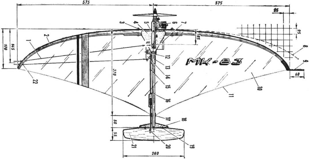
Drilled two holes on the docking station, insert the two trim tubes D16T 5×1 mm. will pass Through them bolts dural motor. The outer end of the wing wire carries the load brake compensates for the weight of the cord and prevents flies the model in a circle at the loss of cord tension control, inner copper tube 3X1 mm for the passage of cables.
Tail feathers from balsa and light ply plates glued macalintal paper on Amalia. The wheel height can be done from the wafer packaging foam, turn over her balsa rails and cable obtenu thin paper in PVA. Kleiv in the grooves of beams plywood bracket rocking control, install it on the model and choose the length of the thrust which arches from duralumin wire Ø 3 mm. Hog rudder plywood.
It remains to pull the edge-on a string (it is better to make a steel cable Ø 0,6—0,7 mm) and hang the camera Mylar film on glue “88” or “Unique”. Achieving a uniform stretching of the film, set on the corners of D16T 15×15 mm, ground down to a size 10X12 mm, engine. For this model, which has a very light tail section, fit motors with front-wheel distribution of the “meteor” or CSTIM is 2.5. The best option is the use of modern improvised fighting engine of lightweight construction.
Design template for bending rails edge.
In hole Ø 10 mm beech inserted pins of the same diameter with a length of 60 mm.
Engine mount (aluminum profile).
If the engine is heavy, the load beam end to the center of gravity was specified on the drawing. Don’t forget about the hook for hanging thread tape and alphanumeric identification labels.
I would like to note that a similar apparatus to the maximum extent meets the requirements of the school and school competitions in air combat, the rules of which are stipulated maximum working volume of the engine 1.5 cm3. To build such a model, reduce all the principal dimensions are 1.4 times. The most appropriate is the engine “swift”, produced by our industry standard.
V. TIKHOMIROV, master of sports of the USSR
Recommend to read
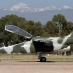 FMA IA 63 Pampa (Argentina)
Development of combat training aircraft "Pampa" began in 1979, the Design was made on the basis of the aircraft "alpha jet", with the involvement of the company "Dornier". In 1981 began...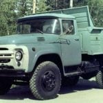 NTTM — THE VILLAGE
THE CAR ROOF. For transportation of bulk cargo: flour for bakeries, cement on construction sites, fertilizers on the field — in recent years increasingly used cars with special...
 It would seem, what new it is possible to invent models of air combat! Undoubtedly, these microstrobili today meet all the requirements of transient encounters over the track. No wonder even top athletes can be heard that the best equipment they are not necessary, it’s just a systematic preparation for the training athlete.