A dead end? After all, the conditions were set out conditions of training in the gym. Compromise is not wanted… And electrolet would have remained a toy, if not I got the idea to use the unusual method of increasing the tension cord. Enough to install on the fuselage perpendicular to the wing curved plate, creating when it is blowing horizontally directed lift force, once solved all the problems! The tension created not only s flight, already standing on the ground with the inclusion of the engine model you tried to leave the circle.
The design of the plant:
1 — spinner, 2 — nut, 3 — propeller, 4 — bearing sleeve 5 — bearing, 6 — impeller, 7 — boss (6 pieces evenly in diameter), 8 staff of the permanent magnet ring, 9 — the anchor of the engine 10 to the frame with the brush device 11 , a flexible wire from rocking, 12 — case, 13 — bearing, 14 — insert 15 — remote sleeve, 16 — bow frame, 17 — insert-fairing.
A template to build the profile of the wing:
1 — leading edge, 2 — filler polonaruwa, 3 — piping 4 — shelf spar, 5 — the wall 6 — a wall the rear edge 7 of the rear edge.
Wing design:
1 — piping tip, 2 — tip, 3 — leading edge, 4 — rib, 5 — polonaruwa, 6 — spar, 7 — sub shell, 8 — lug, 9 — rocker 10 — the rear edge 11 — the wall 12 — motor of the flap, 13 panel, 14, 15 — border 16 — filling, 17 — vertical bar, 18 — struts, 19 — trim the tail boom, 20 trim panel.
Now you can think about maximum zoom flight properties, electric properties of sports equipment. Plates are allowed to leave the flight speed around 7 m/s, which corresponds to the time required for each circle is about 5 s, how large pilotage. And in order to achieve the desired relative radius of the passage angle of a square figure, was required to significantly reduce the load on the supporting surface. This increased the wing area by its width.
Based on the construction of the new lectrolite took a good scheme bouzouki-pilotage, published in “M-K” № 11 in 1983. The almost complete absence of the fuselage on this model allows you to save a lot of weight. Pilot properties is greatly improved due to the introduction of the developed area of the flaps and the horizontal tail in larger sizes.
Focused on the design of the propulsion system. Primarily used to set the motor type DK-5-19. Easy, resourceful, they made almost a four-fold overload voltage. But this perekal made itself felt. Strong tumor ka brushes and a large operating current heated the motor so that the melted plastic housings of collectors and otpaivali album from the brush holders.
We used the option offered by the journal — adapted been ship modeling engine. Instead of trying to carve a new magnesium alloy case and a back steak, decided to completely abandon those elements, leaving only the permanent magnet and the armature from a regular engine. But can’t anchor to just spin in the air? Of course not! But the engine block can be a paper tube wound from several layers of paper on a metal mandrel, it — the nose of the fuselage. Enough paste in the tube two textolite lightweight frame carrying the bearing sleeve and brush device of the motor DK-5-19, as the engine will be a direct part of the model. It is perfect! Not a single superfluous detail. Paper tube-building will help to choose the necessary alignment of the device by clipping her rear end, sitting down on the toe of the wing.
The conditions of cooling of the engine components are also “on top”. And the magnet and the armature does not have the shims prevent the heat loss flow of the RAM air, the path is of minimum length. If we add a small impeller, fan, drives the flow through the engine, it will be able to significantly raise the capacity of the motor supply voltage is increased. Cooling by the fan more efficiently than from the incoming flow. The inboard sections of the propeller as a fan can not work, they only obstruct the inlet portion of the housing.
A few words about the plates and the empennage. First flights on the new model showed that between these elements there is a relationship affecting the constancy of the tension cord, the fact that the plate with a strongly curved profile, in addition to the significant lift force when blowing create and a great time unwrapping the model is the loss of tension cord inside of the circle. Thus the use of them would be meaningless if the COP able to compensate for this moment by the removal of the fins.
To improve visual perception of the plate are made of transparent plastic, in flight they are almost invisible, especially in the sports hall. The bottom edge is the site of attachment of the spinner wheels. Need for additional front of the chassis there is enough to prevent side plate bending by installing a pair of braces.
The circuit control model:
1 — wire flexible power, 2 — rocking chair 3 — termination pull, 4 — pull rudder, 5 — pull the flaps, 6 — plug the drive flap, 7 — pylon rudder.
Design of horizontal operanda:
1 — the front edge of the stabilizer 2 stabilizer 3 — the ending of the stabilizer, 4 — the trailing edge of the stabilizer, 5 — front edge wheel, 6 — insert for mounting the horn, 7 — Elevator, 8 — trailing edge, the 9 — ending. Flaps and Keeley design is similar to the horizontal tail.
System cord:
1 — flexible wire from rocking, 2 — thin-wire, 3 — wire enlarged cross-section 4 — stranded wire, 5 — handle, 6 — two-core cable to the battery and the switch
It should be noted another positive factor from the use of wing-like elements, is the compensation torque of the engine. In terms of “electroplater” with a relatively small tension cord motor torque has a significant influence on the behavior of the model in the upper parts of the hemisphere. Plate, taking the “over” almost the entire flow from the rotor, return to the model of the moment, almost completely compensating for it. Suggest you experiment with the angle of installation of the front “fins” with respect to the axis of the plant. The fact that the stream of air behind a propeller has a significant twist, so for efficient straightening and at the same time to create maximum power on the exit from the circle you must find them individually for each plate, upper and lower.
It is interesting and system cord. From significant losses associated with the need to use them for copper wire minimum diameter was removed through the use of composite yarns. The end portions having the greatest resistance to air flow, is made of a wire of PEL d, 0.25 mm further to the handle of PEL d is 0.5 mm. Now the loss of tension on the cords will be at the current 2.5 And not more than 3 V.
V. TAMONOV, head of airmodelling mug
Recommend to read TO GO UNDER WATER OR DIVE? At that time, as a little clunky, but gained confidence with their performance of the submarine Holland quickly began to spread from America around the world, Europe remained a private... RIPPER HIV In recent years, more and more supporters of progressive subsurface tillage. Individual gardeners produce it with a fork. One time there was a Ripper Berezutsky. In contrast, the... 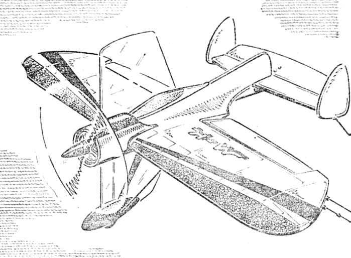
 It is not easy to be “protanium”! As in any other class of modeling, the success of his performance depends on the number of workouts. And how to look forward to the end of the long winter to come up with a model for the wet melting snow from the track and begin a new sports season! He flies quickly: in only five months. The rest of the year can only be used for the construction of new equipment. So if we had to continue training all year round! But it is hampered and the lack of winter sites suitable for starting, and poor performance nitro engines in the cold. And the use of such “exercises” stiff arm a little.