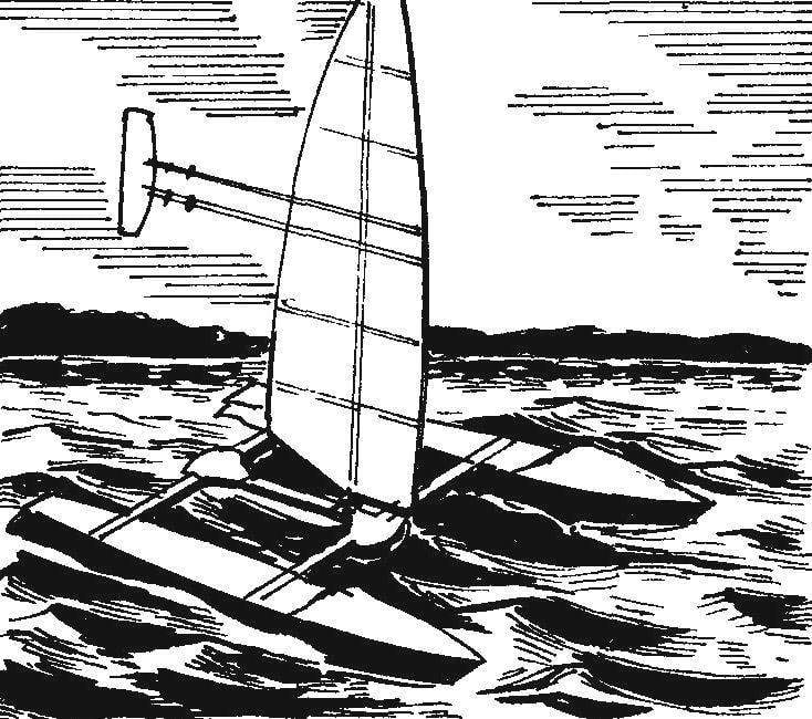
 Model of a catamaran-class “P” with a sail-wing. Few people remember that the apparatus used for movements the aerodynamic forces, was created more than five thousand years ago. It was a self-propelled vessel with a sail propulsion, which worked exactly the same as the wing of a modern aircraft. The only difference is that the lift force of the aircraft wing pointing up vertically, and the pulling force of the sail horizontally. In fact, the movement of the sailboat is the same flight, only on the side.
Five thousand years mankind took to turn the sail wing aircraft. Some half a century — to turn airplane wing in a propeller or wheel of a classic yacht or yachts.
The effect was stunning. Speed parameters in the experimental yacht with a rigid sail was not worse than motor boats. The fact that the regular sail is not too good “aerodynamics” — at least compare the glider with its sail-wing glider with a record: the first aerodynamic quality barely reaches 8 units, and the latter over 40!
However, higher quality has a wing with a PLANO-convex or concave-convex profile. But for the sailboat had to use a wing with a symmetrical profile, who had the worst pulling properties, but the same worked when driving both on the right and on the left tack.
Ship modelers out of the situation easily—they have installed on their yachts wing, PLANO-convex or concave-convex profile and with a change of the gals just turned it upside down. Well, a full sized yacht restless, the inventors equipped the wing, changing the profile due to deflection of the flap.
Good results showed and yachts with a relatively narrow symmetrical wing profile, more like a very wide mast in combination with an equally narrow sail with hard battens, carrying out the function of the flap.

The geometric scheme of the catamaran class “P”

The design of the catamaran hull (the planned projection of the shell of the case conventionally not shown):
1—spanset No. 1;2—spanset No. 2;3—keel; 4—the bottom of the keel; 5—frame№4;6—keel beams; 7—frame № 5; 8—transom Board; 9,16—base connecting pins; 10—a connecting stud; 11—frame №6; 12—stringers; 13—scupper; 14—frame №3; 15—shell case; 17—the airlock steering pen
Today we introduce modelers with a model sailing catamaran-class “P”, equipped with swiveling sail is a symmetric wing profile. I think that the design of the sailboat will be of interest to fans of “big” sailing.
A few words about the principle of semioriental sail-wing. Take a look at a geometric diagram of a catamaran—in addition to the hinge installed wing, the aerodynamic system includes a stabilizer is exactly the same as on the classic glider—which automatically sets the sail-<a snout at the optimum angle of attack relative to the direction of the apparent wind.
The model design is not too complicated. Catamaran hull vyklevyvajutsja on the wooden disc from fiberglass and epoxy binder, and the first formed the lower part of the hull to deck) and then the top. The thickness of the shell of the hull about 2 mm.
After vyklicky upper and lower parts are adjusted to each other and shell are enhanced by set—plywood frames, keel beam and stringers. Mandatory on frames should provide the scuppers and the transom hole with the drain plug within the body of water.

Scheme of the sail-wing

Hinge joint of the wing:
1 —the front edge of the wing; 2—spar; 3 —chord; 4—rear edge; 5—a lining of a taper of the wing; 6—longitudinal beam of the bridge of the catamaran; 7—a lining; 8,10—M8 nut; 9—root polonaruwa wing; 11—bearing casing of a hinge wing; 12—axis hinge wing

The bridge:
1—the front beam of the bridge; 2,4—lining; 3 —longitudinal beam of the bridge; 5—rear beam bridge; 6—the cradle
In the frames # 3 and # 6 set of wood pasted them in with steel studs—they are designed for the connection of buildings with a bridge. At this stage, the corps installed a plywood keels, then the decks. All these details are fixed with epoxy glue, to which you are adding any powdered thickener—cement and gypsum to flour and starch. Tail feathers are cut out of plywood 6 mm thick; profile of the feathers flat, symmetrical, with a rounded front edge and pointed rear. The installation of the pen in each case is carried out using a M5 threaded studs and nuts-lamb.
Ready-made body are puttied, sanded and painted with enamel of suitable color.
The bridge shaped like the letter “H” made of pine slats and enhanced pads of 2 mm plywood. The Assembly of the bridge is made using epoxy glue. The finished bridge is covered with several layers of varnish parquet.
The sail-wing model aircraft is produced by classical technology, the Frame of the wing consists of dvuhromovo spar from pine slats, pine the front and rear edges, and a set of ribs. The last best cut from the regular school lines with a thickness of 2-3 mm.
The beam attachment of the stabilizer is also cut from lines 3 mm thick Central part of the wing is sutured fake a 1.5 mm veneer. Between the shelves of the spar at the root of the wing is fixed with glue beech block with a drilled Central hole with a diameter of 8 mm, which is the bearing of the hinge wing.


The sail-wing:
1 —root polonaruwa; 2—the bearing housing of the hinge wing; 3—spar; 4 — ribs; 5 — the leading edge; 6,8—lining; 7—a lining of the Central part of the wing; 9—rear flange; 10 — lug; 11—beam stabilizer; 12 — screws-fasteners; 13 — stabilizer bracket; 14—stabilizer; 15—a lining of a taper wing
The wing skin is Mylar film which is attached to the frame of the wing cleek type “BF” or “Moment”. The stretch paneling is produced using a conventional electric iron.
The stabilizer is cut from dense foam stamps “PS”. It is a flat plate with a thickness of about 8 mm, the front of which is rounded, and the rear pointed. For attachment of the stabilizer is designed to beams embedded in his arms—their fixation on the beams is carried out by four screws, glued with epoxy to the brackets. Nuts for connection is not required—the beam just a little apart, and the screws are omitted in the holes. This method of fixing makes it easy to move the stabilizer is “upside down” in launching the catamaran another tack.
Before running the model, you must ensure that the catamaran with the removed wing-sail from the push arm moves strictly in a straight line, otherwise will have to adjust the heading with the rudders.
Before driving the catamaran needs orientation in accordance with the planned course, and the stabilizer should be set so that the angle of attack of the wing relative to the wind was positive. When the model is run another Hals stabilizer is turned upside down.
On the course the wind—when the wind is blowing strongly in the stern of a sailboat—the wing is installed across the flow direction and is fixed in this position using the mainsheet attached to the aft edge of the sail.
Methods and materials for the manufacture of shells and wings, described above, is not the only one. In particular, a very good hull and sail-wings can be made of foam. The first pasted with two layers of fiberglass, and the second is only primed with epoxy glue.
I. TEREKHOV


