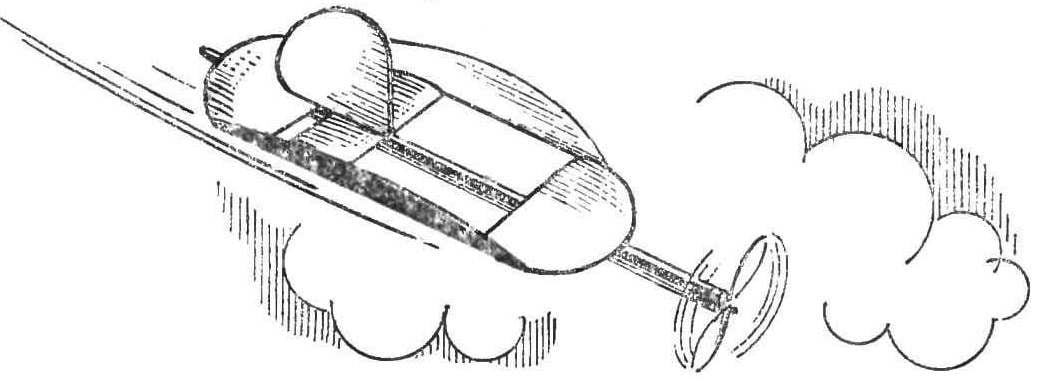
 Victor E. Marina from Rostov-on-don from a young age engaged in the construction of models of free flight. In recent time, leading a circle of aircraft modeling on obsut, he became interested in the structures with circular drainer, discreto. However, to achieve good results for a long time could not — flying “plates” were heavy, clumsy, and most annoying, bad flying.
But the thrust of creative research eventually led to success — a scheme of a slotted disc flying devices with acceptable characteristics.
Models built according to this scheme, look quite unusual. Wing they have the most incredible shapes: round, triangular, square and other “geometries”. When they take off and begin to float in the air, one wonders: how is it possible? Published in this issue describe several designs V. E. Marinova exhaustively, in our opinion, the answer to this question.
For drawing the slotted discrete building a pair of square and circle, square and triangle etc. a square is a frame on which to mount the whole system of wings: front, tail, right and left side (Fig. 1). But the disk with a square gap has a significant disadvantage: weak attachment of the nodes in the connection points a — d. Therefore, slit is recommended closer to the front or tail edge of the disc, guided by the following parameters: fixed — width side wing (N) D/7, where D is the diameter of the disc; length (A) 5D/7; variable — width front and rear wings (b) from 3/14 to 3D/7.
Using these data, it is easy to design a variety of system models. For example, the four-wing will discole (Fig. 2). He has good flight characteristics: lowest weight, good climbing, stability in flight, ease of manufacture. This system is suitable for the construction of model aircraft of almost all classes. Increasing the width of the front wing to 3D/7, you can design and cord model.
The sizes are from 200 to 850 mm, the structural material of the most diverse, up to the paper.
Further development of this system was the addition of a fifth (the second front) of the wing, which is mounted inside the cracks. Changing its location, you can create a new diagram (Fig. 3 — 5). All of them, differing from Each other in appearance, equal in flight performance.

Fig. 1. Schematic diagram of discrete:
1 — front wing, 2 — tail wing, 3 — wing, right-side, 4 — left side wing.
Fig. 2. The four-wing will disconet:
1 — front wing, 2 — tail wing, 3 — wing, right-side, 4 — left side wing, 5 — stabilizer.
Fig. 3-5. The discrete with the fifth wing (second front):
1 — rear wing 2 — the second front wing 3 — tail wing, 4 — right-side wing, 5 — left side wing, 6 — stabilizer.

Fig. 6. Ring model “Dream of science fiction”:
1 — rear wing 2 — the second front wing 3 — tail wing, 4 — right-side wing, 5 — left side wing, 6 — disk, 7 — stabilizer.
Fig. 7. Slit equilateral triangle.
Designation of positions the same as in figure 2.

Fig. 8. The model with the front wing in the shape of a spear.
Designation of positions the same as in figure 2.
Fig. 9. Slit square.
Designation of positions the same as in figure 3.
Here is a typical diskret this scheme (Fig. 3). The transverse form of the system — trough. A keel mounted on the fuselage, the tail or the second front wing and does not protrude beyond the perimeter of the circle. Aileron, flaps mounted on the inside.
Great interest in children causes round design with middle slit — type circular model, which we called “the dream of science fiction” (see Fig. 6).
The wings have a width of D/7. In the center of the disc a spherical or flat shape. Optional on the second front wing to make flaps, which need to go down (about 5°). Design size 350— 560 mm. Front and tail wings, it is desirable to build a profiled, side — flat profile.
One of the varieties of our slot systems — slot equilateral triangle (Fig. 7). Model speed. The wings are thin profile, the tail has a width of 1/7l, where l is the length of the base of the triangle. The fuselage is tubular or square truss section length 1.4—1.5 l. In a pinch you can use motor ravine. Screw pushing, freewheel Ø 0,51 in increments of 1.5 D. Upon landing, he breaks down often.
The most popular among guys is the model with the front wing in the shape of a spear (Fig. 8). On request it is possible to make flaps. The dimensions of disallow from 200 to 360 mm. Small models are made from dense paper in a simple frame of pine slats or veneer. The base of the side wings, giving them the angle of attack, stiffness, coat with glue.
It is of great interest to slotted square (Fig. 9). It flies faster than the other models. Screw Ø 0.5 D step H of 1.7 D. Without a second front wing model is unstable.
Practical recommendations. To make the wings slotted disallow you from an inexpensive material: pine, basswood, veneer, foam, paper. Discs with a size of 300-500 mm can make better foam, and 500-850 mm — stacked design-profiled. Wings can be assembled on a simple frame of pine or veneer.
For making wings from foam a template from sheet metal or cardboard. He does so. Draw on a sheet of paper or cardboard part of the projected disk. Connect two points of a circle by a chord equal to 5D/7, and then cut the resulting segment pattern.
For billet front and rear wings must be reduced. The template for the second front wing — rectangular shape with a width of D/7.
Before beginning work on the wings discolite make a drawing of the model in natural size, and it fit the templates. Then cut out foam wings, sand paper and give them the selected profile. At the front of the wings he was a regular, slightly concave in lower part; at the side — flat, thin; the tail is also normal, but flat on the bottom.
Collect the model on an Assembly Board on which is pre-make a drawing of discrete; the contour of the pins reinforce the wings; the tail first, then front (tucked under the toe of the match). Side wings connect them, giving an appropriate angle. Last mount the second front fender.
Glue model glue BF-2, but the best epoxy. The fuselage can be of any design: from simple motor ravine to the typesetting system (models with rubber motor dimensions 1.5 D, the screws are about 0.5 D increments of 1.2—1.5 D).
Tighten the wing to the fuselage with rubber strands. The center of gravity must be in the 35-38% of the sock drive will depend on the type plate.
V. MARINOV, Rostov-on-don


