
 Our journal № 8, 1977 published drawings and gave recommendations for the production and painting of body, interior cockpit and chassis system of the minibus RAF-2203, produced by the Jelgava plant of vans in the Latvian SSR. These materials were designed for young designers who are building-models of cars.
Today we publish an illustration of the General form, detailing the undercarriage and a brief description of the model with the motor of the van RAF-22031, built by student from Novosibirsk Sergey Lavrenchuk in the circle of experimental aviamodelirovaniya Cute plant named after V. P. Chkalov. In the preliminary heats model has a top speed of 38.5 km/h. When you create a copy of the modeller had its engine and materials, somewhere to retreat from the proportions of the prototype.
The model consists of a body and chassis.
The body is made by lime or pine blank from sheet metal of 0.3 mm thickness. It is collected from the roof, two side, back and front panels. They give shape to disc, then cut out door and window openings. Made the same door. The panels are interconnected by soldering. Front and rear set of lights CM-3, simulating the headlights, sidelights, direction indicators, tail opt.
Wiring of lighting the same was published in the journal “modelist-Konstruktor” (number 11, 1977).
On the roof of the model installed another bulb. Closing her cap is made from Plexiglas and painted in orange napolcom cysts.
Chassis includes frame, front and rear axles with pendants.
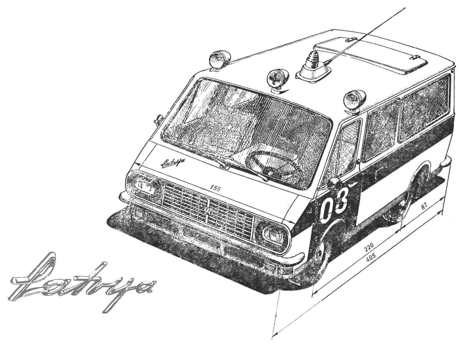
Fig. 1. General view of the model of the van RAF-22031
Frame the model of flow box made of tin. The technology of manufacture of such frames are given in the description of the model GAZ-66 (“M-K” № 11, 1975). The frame is fitted with: bracket motor mount DP-3, the intermediate bearing and the hinge of the rear springs.
Front suspension is independent type, spring. It consists of a frame, upper and lower rods, coil springs, axle, bracket axle shafts, and various fasteners (screws and nuts M2 and M3).
The subframe is milled from a D-16T. From the same material used in all parts of the front suspension.
Wheel machined from a D-16T. Inside front wheel is installed sleeve with two bearings (No. 1000094 Ø11X4 mm). With hubs they are fastened with two screws no.3.
Carter of a reducer of the rear bridge is built from three brass parts: two side sleeves and front bushings for installing ball bearings (Ø 9X3 mm) pinion gear. Axis fixed thereto the driven gear rotates in the housing on two ball bearings Ø11X4 mm. Sleeve bearing pinion (gear ratio 1:1,46) soldered to the halves of the rear axle housing tin solder. Between the halves of the gear casing are connected by screws with M2 nuts.
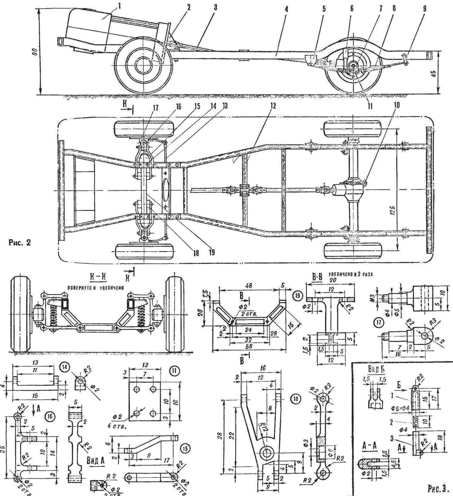
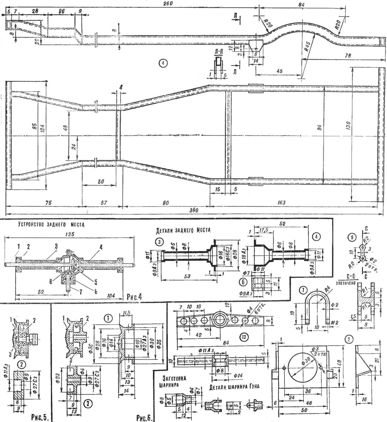
Fig. 2. Chassis model:
1 — motor, 2 — bracket, 3 — propeller shaft, 4 — frame, 5 — yoke, 6 — absorber, 7 — step ladder, 6 — spring, 9 — ring, 10 — rear axle, 11 — plate 12 — Travers, 13 — rod, 14 — eye, 15 — upper arm, 16 — pivot strut, 17 — knuckle, 18 — lower control arm, 19 — beam front suspension
Fig. 3. Details of telescopic shock:
1 — Cup, 2 — spring, 3 stock.
Fig. 4. Rear axle Assembly:
1 — drive axle, 2 — bearing (Ø 11X4), 3,4 — side sleeves, 5 — driven gear, 6 front hub, 7 — shank, 8 — pinion.
Figure 5. The front wheel hub Assembly:
1 — the disk wheel 2 — hub, 3 — retaining bolt.
Figure 6. Hub rear wheel Assembly:
1 — the disk wheel 2 — hub, 3 — retaining bolt.
For spring used spring steel with a width of 5 mm. you Can use the spring stroke or bout of alarms.
Each spring is assembled from 8 pieces. At the ends of the crankshaft soldered sheet brass or steel tube internal Ø 2 mm.
Earring of a rear spring made of D-16T. To the rear axle springs are mounted by means of four ladders and two plates.
The shock absorbers are assembled from copper tubes and coil springs. The inner diameter of the workpiece buildings shall not exceed Ø 3 mm shock Absorbers attached at one end to the bridge, and the other to the frame using tabs and screws with M2 nuts.
Universal joints articulate of workpieces, machined on a lathe, and cubes, as shown in the drawing.
The casing is fixed on the frame by two M2 screw through the hole under the rear bumpers. At the front of the frame are the hinge on which the body leans forward-upward. To make it easily removable, you can put hinges instead of struts.
After the putty and Stripping the hull primed and painted white. Protecting adhesive tape to the second paper not be white space, cover in red paint the middle part of the body. On it on both sides of the model with white paint is applied the inscription: “Emergency medical assistance” (height of letters 5 mm). The cab doors are also painted in red color and white paint represent the numbers 03 height of 20 mm.
Cord strap is attached to the frame of the model exactly in the center of gravity and through the slot in the housing is discharged to the outside.
The glass body is fixed by means of small pads of tin soldered around the perimeter of the window opening from inside the body. The inner surface of the cabin decorated (88 glue or rubber) pieces of embossed paper “under the skin” of the sets for manual labor.
Power (battery) lighting and warning lights on the roof of the model is placed on the floor of the case near the partition separating the cockpit from the cabin. It should be there in all competitions.
V. KUZNETSOV, head of the society
Recommend to read
 OLD FRIEND
"Soap", "the Hunchback", "Fafik" — not once nicknamed little brisk Zaporozhets 965-th model. Many of us that he began his "auto" biography. Not all, however, know how motley was the... THE SNOWMOBILE RIDE YOURSELF!
When winter comes and the snow is "fluffy blanket" covers the ground in many areas, the only vehicle able to overcome it "fluffy blanket", it becomes tracked all-terrain vehicle or, more...
