Then the frame is removed from the pile; Reiki stringers and keel beam treated sandpaper (medium grit) to match the contours of the frames. Space (place) and cut out of plywood with a thickness of 1.2 mm and bottom parts of the hull that is glued to the frame, securing it again on the Board of the bench. After that, the case is removed from the pile and the same way mark of the workpiece sides and deck. The last cut a window to access the parts and knots in the inner part of the housing. Window edging around the perimeter of the rails. The Board is mounted on the frame. Set boss handlebar mounts and engine mounts. Before fixing the deck inside the hull two or three times varnish, and the outside — once the nitrocellulose lacquer or two-component parquet. The bow section are cut from basswood with a small allowance and glued to the 6th frame. After that, install the deck. The model’s nose is treated to the exact contours of the whole body is covered with nitrosatable (homemade or industrial production). A good coating is obtained on the basis of light nitro, talc or baby powder and nitrobacteria. After drying, the surface is sanded with fine sandpaper. At the bottom of the drilled holes under the axis of a rudder and stern tube. The axle is made of duralumin of the spokes 0 of 2.5 mm. Graded use branded or home-made, made of duralumin tubes of 0 8 mm and a wall thickness of not less than 1 mm. Round file the hole in the hull to fit the deadwood, then the tube is glued. Between the keel beam and deadwood put the wedge of 2 mm plywood. The output of tube paste over the layer of glass of a thickness of 0,1 -0,15 mm or a cloth. The external body is painted with nitro enamel. The rudder was cut from 2-mm lime and sheathe from two parties of the 1 mm plywood. In the hole of the boss close up of the steering axis.
For the convenience of further work, it is useful to make the construction from 4 mm plywood and pine strips 3x10x380 mm Park tool tray-stand, and the contours of the plywood stands, I repeat the contours of the hull in the places of the 2nd and 5th frames. On the seats stick the soft lining of thin felt or penoplena. Ready stand cover two or three times a nitrocellulose lacquer or nitro enamel.
Fig. 1. Model motor yacht:
1 — feed flag 2 — feed fence, 3 — lodgements boats, 4 — boat, 5 — beam crane, 6 — bracket mast 7 mast, 8 — gaff rig (top view not shown) and a 9 handrail, 10 — trap, 11 —navigation side light, 12 — canopy 13 — door cutting, 14 — spotlight 15—side panel add-in, 16 — side grab handle, 17 — buoys, 18 — spire anchors, 19 — cap rail, 20 — anchor, 21 — pipe deadwood, 22 — wedge, 23 — thruster, 24 — the wheel. 25 — the inner wall of the wheelhouse, a 26 — floor cabin.
R and S. 2. Hull and superstructure:
1 back wall, 2 — rear frame superstructure 3, 13 — stringers, 4 — roof aft, 5, 8 — frames of the deckhouse, 6— side, 7— back wall of the pilothouse, 9— frame roof 10 roof 11 — the frame of the bow, 12 — roof bow, 14 — framing stringer, 15 — front wall, 16 — bow, 17 — gusset plate keel beam, 18 — the front part of the deck, the 19 — additional keel beam, 20 — keel beam, 21 — motor mount (Linden, 40x40x35 mm), 22 — motor 23 — coupling 24 — bilge stringer, a 25 the inner wall of the pilothouse, 26 — gender of logging, 27 — deck stringer, 28 — cording 29 — floor fodder. 30 — boss handlebar mounts (Linden, 20x30x20 mm) 31 — feed enhancement Board, 32 — aft deck, 33 — transom. (Design details are made from the following materials: positions 1, 4, 6. 7, 10, 12, 15, 25, 26, 31 and 33 from 1 mm plywood, position 2, 5, 8, 9, 11, 17, 18, 29 and 32 — of 2 mm plywood, positions 3 and 13 is made of Linden slats cross-section 3×3 mm, positions of 14, 24, 27, Linden slats cross section of 3×5 mm positions 19, 20, 28, Linden slats cross-section of 2×10 mm.)
Fig. Z. Mast Assembly:
1 — bracket (lime, 10 mm), 2 — lining (plywood, 1.2 mm), 3 — mast (pine, 8x8x150 mm), 4 — gaff rig (plywood, 1.2 mm).
Fig. 4. vykroiki frames of the case (the numbers correspond to the theoretical cross sections of Fig. 2).
R and S. 5. The pattern details of the model (numbers correspond to the positions of Fig. 2).
The design of add-in mini-yachts — combined. Build it is as follows. The rear frame connects with the floor and install sides. On the slipway by marking consolidate all the frames and stringers combine them into a single frame. Then put prosperous cuttings and sidewall of the superstructure. In the bow attach front wall. Next, mount: roof of the pilothouse, bow and stern parts, Paul wheelhouse, inner and posterior wall of the deckhouse and a rear wall of the superstructure. Around the perimeter of the entire structure bonded to the stringer. The add-in is removed from the pile and treated with sandpaper. Inside and outside primed it two or three coats of nitrocellulose lacquer and coated with nitro enamel. Using transparencies mimic glazing. It is cut out the visor on the wheelhouse.
The mast is foldable, which is convenient when traveling on water. Do it alone ready node set on add-in. Fencing and handrails solder from a 1.5 mm brass or copper wire. The boat is cut from a block of basswood. Ladders, doors and side navigation lights are glued from thin cardboard or drawing paper (two layers). Searchlight, life rings, bollards, anchor windlass and anchor are made from the material at hand (wood, polystyrene, thread, etc.). The flag of the subtle matter or color film. All the small parts neatly painted and set on the model according to the drawing. On the mast nylon thread mimic the wiring of the rigging.
As the base powerplant would be the best motor for Mabuchi type-380 RS and semielementnyh battery Nickel-cadmium battery capacity 1.2 A h Equipment radio control is used for steering and speed control of the motor.
The colors that paint the boat: waterline — silver; body above waterline — white or light gray. Under the waterline — green or red. Deck “boardwalk”, unpainted. The boat is white with a red bottom, lifebuoy red or orange. Side lights: left — red, right — green.
When balancing the model select the position of the batteries, as the heaviest parts. To protect the elements of the control equipment from moisture blocks are Packed in plastic bags. In order to avoid overdischarge of the battery chassis and the subsequent shutdown of the entire control system, it is recommended to use a separate power supply control and motor.
S. GONCHAROV, engineer
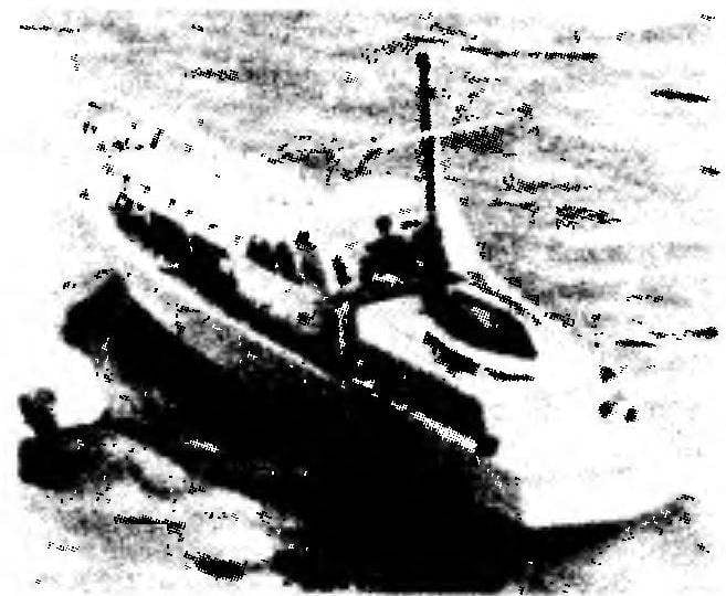
Recommend to read “FIFTEEN PUZZLE” ON THE WATER Water motorcycles, or scooters, are very popular among water motor sports enthusiasts and athletes. This type of transport has expanded the range of watercraft, contributes to the... THE BED-INVISIBLE The proposed distribution network of the other transformable design for sleep have one common not wealth: they allow you to rest only in "Spartan" conditions. Meanwhile, this...  German river motor yacht “bar-new” (Warnow) was the inspiration great procopii, equipped with an electric motor and two channel radio control equipment. She was repeatedly reproduced by modelers and enjoyed great success at competitions and demonstrations. In the absence of radio equipment with the model it is possible to speak in the classroom “bramahadev”. The design model is simple. With its manufacture and Assembly can handle every aspiring constructor of ship models. The case is of classic design, stacked wooden. Collect it on the epoxy. Mounting up the keel on a flat Board-berth with a fixed drawing with the layout of the centerline and locations of frames from the 1st through the 6th. All of the parts of the frame previously marked in accordance with drawings, cut out and treated.