
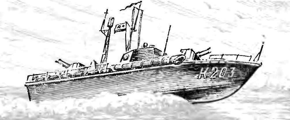
 The proposed model torpedo boat was built by students in the 5-6-grade in ship modeling circle of the Moscow city club of young sailors, rivermen and explorers. In both variants rezinomotornaya and two microelectrophoresis — miniature torpedo boat had good speed and stability on the course. The model is simple in manufacture, does not require scarce materials. Young modelers, speaking at the Moscow urban competitions, repeatedly won prizes.
To work on the model (Fig. 1) will need the following tools and materials: jig saw, pocket knife or scalpel, scissors, electric soldering iron, hammer, ruler, pencil, soft brush, plywood with a thickness of 2-3 mm, the bar lime, or any other soft wood, pine slats with a cross-section 3X3 mm (you can rent them from a model airplane kit), thick, but not very thick cardboard, sheet metal, small nails of different sizes, organic glass, thin steel, copper or brass wire, nitrogly, nitroanaline or enamel paint. Depending on the selected option may need round rubber cross-section 1 mm2 or microelectronical that Assembly with the deadwood, propeller shaft and propeller are commercially available.
Case the best thing to do, stacked with cardboard covering, then it comes out light and strong enough. The set consists of pitching frames, six frames, transom, stringers and bow boss.
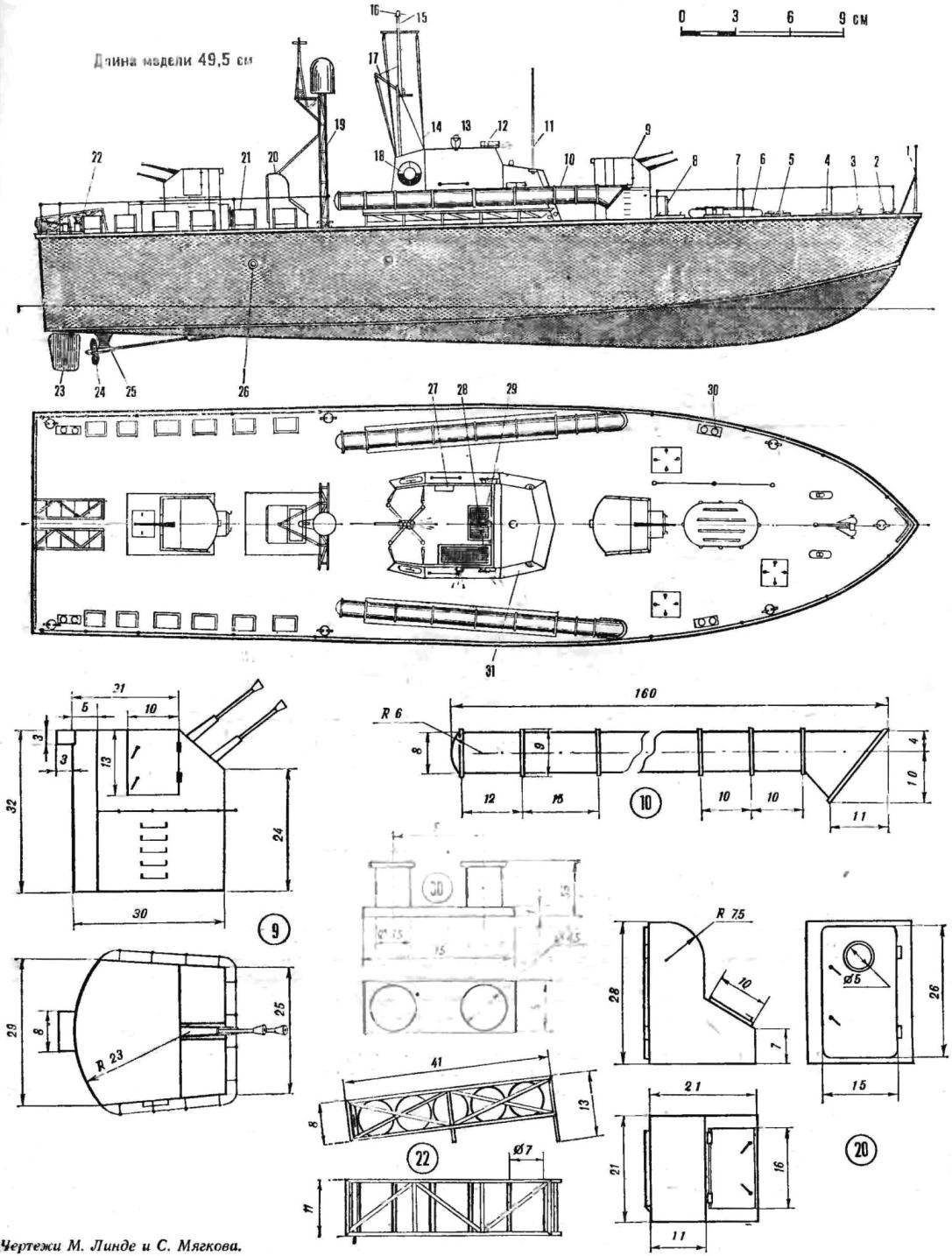
Fig. 1. Model torpedo boat:
1 — bale strap, 2 — duck; 3 — anchor; 4 — anchor fairleads; 5 — cover the hatches; 6 — rail, 7 — liferaft; 8 — fender first shots; 9 — twin gun mount; 10 — torpedo tube; 11 — antenna VHF; 12 — side lights; 13 — signal spotlight; 14 — halyards for flags; 15 — mast; 16 — kotikovye fire; 17 — the gaff for the flag; 18 — lifeline; 19 — mast radar antenna; 20 — porch 21 — depth charge; 22 — rack; 23 — rudder; 24 — thruster; 25 — bracket propeller shaft; 26 — the window; 27—; 28 — Telegraph machine; 29 — steering the steering wheel; 30 — bollard; 31 — cutting.
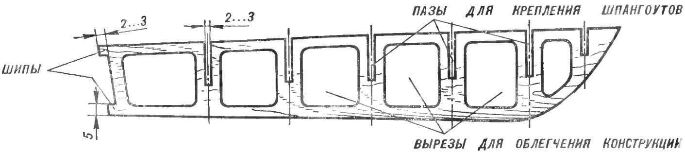
Fig. 2. Keel frame
Before commencing the set out of the hull on a sheet of drawing paper will watertite in full size side view (no buttocks). On a piece of plywood the size of 500X90 mm and thickness 2-3 mm from the projection of the “side” toggle the side view and mark the location of the frames. Obtained on plywood keel frame saw out and lighten, as shown in figure 2. In the place of installation of the frames into the keel frame, the line side of the deck saw the grooves with a width of 2-3 mm (the width of the groove depends on the thickness of plywood, which is made frames). The depth of the groove equal to half the height of the corresponding frame. On the rear transom, do the spikes (see Fig. 2). The finished keel frame carefully apply the sandpaper.
Frames redraw with the projection of “housing” (as it is symmetrical, the drawing shows only half of them). In order to draw a whole, take any width and height of a piece of tissue paper or tracing paper, fold in half, attach the bend to the line DP (diametral plane) on the projection of “housing”. Put on paper an image half-frame. Next, turn the paper, draw on visible on transmission lines of the second part.
Ready template, stick to the plywood or put on her through the carbon paper. All frames, except for the zero and transom, to facilitate. The depth of the groove for fastening the frame equal to half its height. In the corners of each, and the transom with a jigsaw make the grooves for gluing stringers (see Fig. 3).
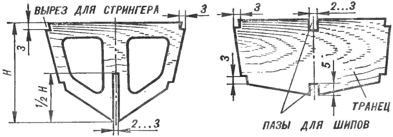
Fig. 3. Frames
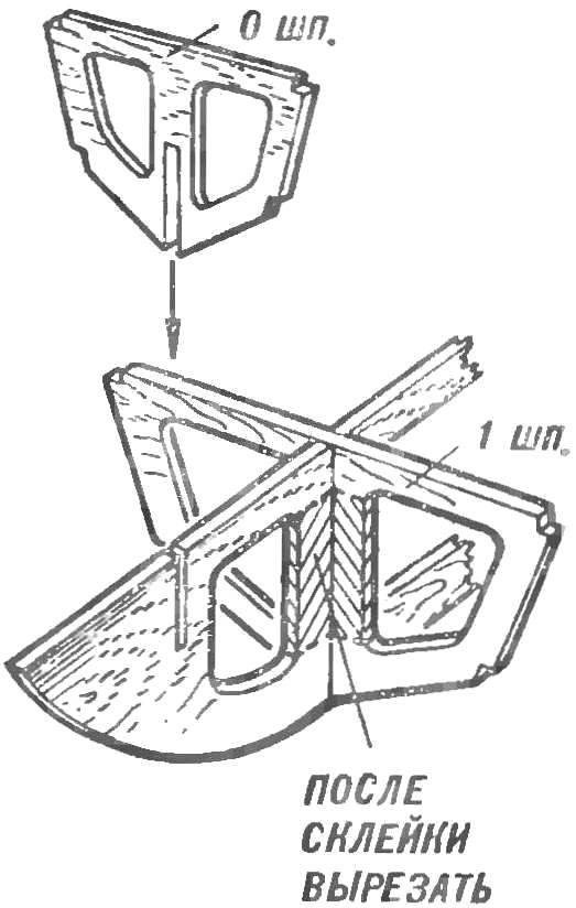
Fig. 4. Installing the frames into the keel frame
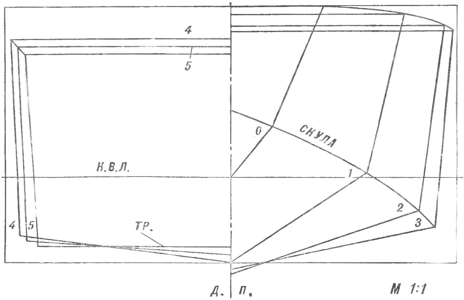
Fig. 5. The projection of “housing”
Now proceed to the Assembly set of the housing. Promazhte glue the attachment. Insert the frames into the appropriate cutouts of the keel framework (Fig. 4). Glue spikes on the transom. Ensure that each element was formed with frame pitching angle of 90°. After that, the angular cut frames and transom attach the rail-stringers, two on each side. Then the hull should be thoroughly sanded, making sure that the stringers after treatment did not go beyond the common line. The excess strips at the bow trim on the zero frame.
The next stage in the manufacture of the body — skin. It is best done in two steps. First, glue the cardboard side, holding the cardboard to the kit rubber band, twine or Bellevue clothespins. Similarly, attach the cardboard bottom. For the manufacture of the nasal boss in the gap between the zero frame and the keel frame on each side to insert and fix by Linden bar. They have little to play for these parts With a large knife and sand paper treat sticks for hull lines. To ease it and have a free place to host the motors and a power connection part of the frames with the keel frame cut with a knife and a jigsaw. After that, the case will remain only the necessary mounting parts.
According to the General arrangement drawing slot at the bottom of the bore for the passage of Davudov. In accordance with the shape of the base engines provide them under the wooden stand and attach it to the motor tin can clamps. The deck made of plywood with thickness of 2 mm. it should be a hatch to replace the electric batteries and access mechanisms.
Add-ins can be made of cardboard, plywood, 1 mm thick solder tin or glue from thin organic glass. Small details make from wire, organic glass or lime. The housing is preferably several times to cover nitrovarnish or nitrocream, and then nitroanaline or enamel paints: the underwater part — in red, green, or black color; freeboard and superstructure — in a ball (steel gray), deck — brown or green.
Paint ball you can get by mixing white, black and blue paint. Basic is white and the number black and blue is determined depending on the desired color schemes empirically.
Rezinomotornaya version of the model for ease of fabrication it is better to make with one screw and the outer rubber motor. In this case, the housing insert the wooden wedges to the mounting bracket of the propeller shaft, and the nasal boss use to install the nose hook for the rubber motor.
When the twin-screw embodiment, power to the motors connect to the front during the course of the model the screws are rotated in relation to the median plane upwards and in different directions, if you look at the model from the stern.
V. MEDVEDEV
Recommend to read
 NOT A DROP SPILLED!
Pouring viscous fluids are often faced with the fact that the jet begins to envelop the edge of the neck of a can or a jar, especially if it is thick and rounded. So the pot does not... IRON WILL BE EASIER
The iron cord when Ironing linen constantly thwarted, trying to get his hot soles. However, if you make a special extension cord, the socket of which to attach under the Ironing Board,...
