 Booster “Diamond-A” in November 1965 into orbit the first French artificial satellite of the Earth. France became the third space power. Length of the rocket “Diamond-A” is about 19 m, launch weight of about 18 tons, the maximum diameter of almost 1.5 m. a Further development of missiles of this series was a three-stage, cross-division stages, the more powerful the rocket “Diamond-In”. Her starting weight of 24 tons, the length of 23.54 m and a maximum diameter of 1.4 m. It is designed to launch communications, navigation, meteorological and other instrumentation.
The proposed model is a copy of the rocket “Diamond-In” made in the Zagorsk district Cute Pavel Vityazeva. Speaking with her at the Moscow regional competition, the young designer won the first place. The altitude of the rocket amounted to 664 m.
The model is built in scale 1 : 40 of the prototype. Official sources were the books by K. V. Morozov “carrier Rockets of space vehicles”, by Peter Stage “Space launch vehicles” (GDR).
Device model
The first stage of the rocket glued on the disc of two layers of thick drawing paper (carpenter’s glue), and then buffed on the lathe at low speed and coated with nitrocellulose lacquer and three coats. Stabilizers — celluloid 2 mm thick. Pre-processed according to the profile and cleaned up with fine emery paper, they are fixed in the housing on two spikes with nitrocream. Welds simulated by one layer of paper. The sheet is double-coated with a liquid nitro lacquer, then the line cut off strips of necessary width and glued them in pure acetone. Gargrota — from soft wood. Sleeve under the first stage engine carved from basswood on a lathe and glued into the hull with resin ED-5.
The adapter between the first and second steps carved from basswood, outside buffed and coated with three layers of nitrocellulose lacquer, and the inside — fire-resistant coating. Design and manufacturing of the second stage similar to the first.
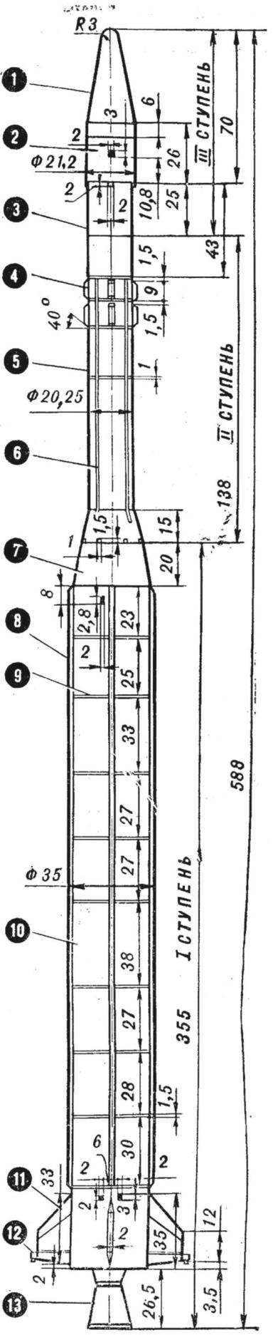
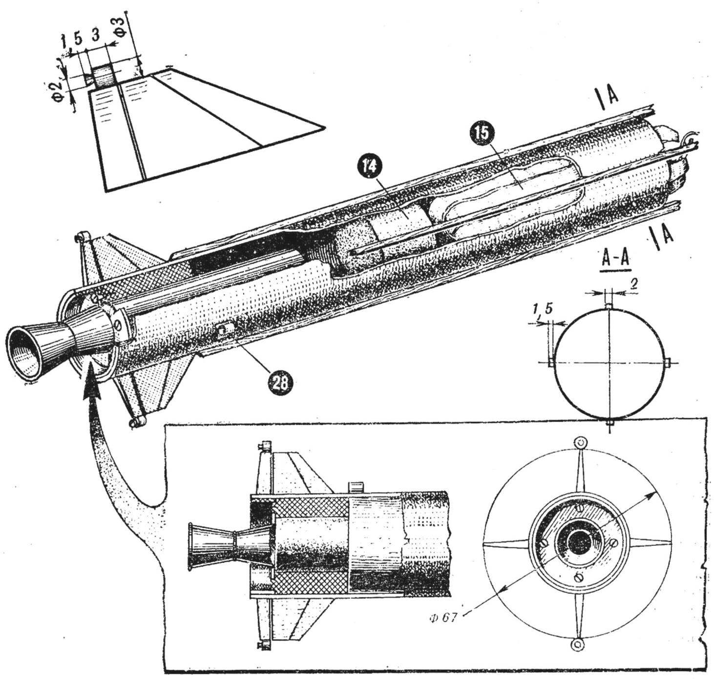
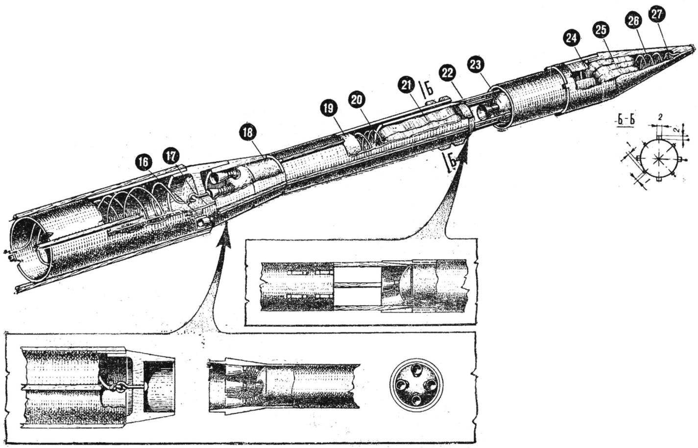
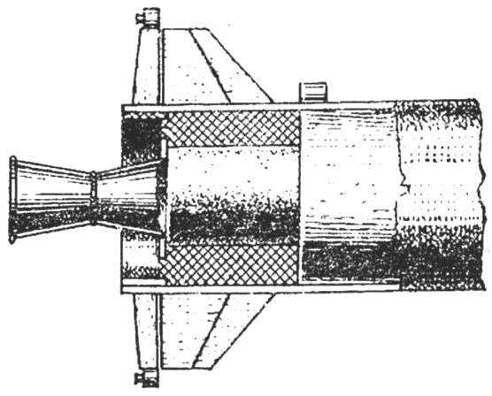
Fig. 1. The appearance and design of the rocket “Diamond-In”:
1 — the fairing 2 — the container to accommodate payload 3 — the case of the third step, 4 — telemetry antenna, 5 — the case of the second stage, 6 — conduit of the second stage (fairing), 7 — adapter, 8 — conduit of the first stage, 9 — simulation of the weld, 10 — the case of the first stage, 11 — Perot stabilizer, 12 — simulating the nozzle 13 jet nozzle to the first stage engine, 14 — wad (easy foam), 15 — parachute of the first stage (Mika-Lenten paper), 16 — seat mount shock-absorbing lanyards, 17 — hook attachment the parachute the first stage, 18 — the second stage engine, 19 — seat mount shock-absorbing device of the second stage, 20 — spring band of the parachute, the 21 — band parachute (fiberglass), 22 — anti-roll slats (pine), 23 — the engine of the third stage, the 24 — seat mount shock-absorbing device of the third stage, 25 — band parachute (fiberglass), 26 — spring band parachute (steel wire Ø 0.3 mm), 27 — hook fastening shock absorbing device 28 — the guide rings (paper).
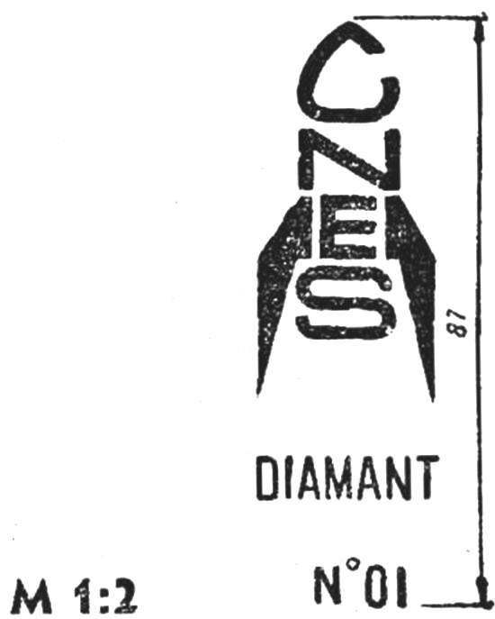
The marking of the missile
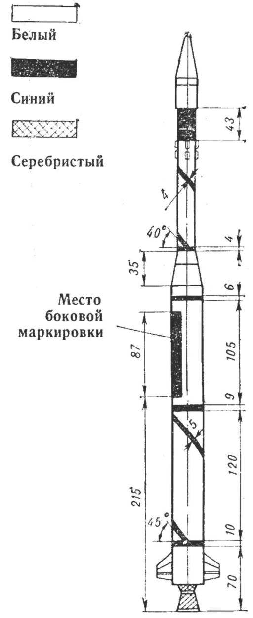
Fig. 2. Scheme of a model rocket.
The body of the third stage — dural, weighing 5 g. (under the new rules, the use of metal elements on the missiles is prohibited. We recommend these parts be made of fiberglass, and the nozzle further coating inside heat-resistant varnish. — Ed.) Fairing is made of dry birch, coated with nitrocellulose lacquer. When working on a model rocket was used a varnish AB-4, cepelak and glue for the skin.
The color “Diamond-In” white, hull is blue helix (see figure).
Flight preparation and launch
For flight and the inclusion of steps built several draft copies of the model, then the entire rocket Assembly. The division of steps is tried to approximate to the prototype. But since the third stage is a almost one fairing, its flight had to stabilize the three pine slats, which are inserted in slots at the bottom of this stage of the model. Length, re;for a cross section of 3X3 mm to about 80 mm. For impulse transmission to subsequent stages tried a few different ways. Eventually settled on the direct delivery of fire flare impulse through an empty tube. To do this, before launching into a tube, inserted one end in the upper part of the engine and the other to the nozzle subsequent stage, peppered black powder in a quantity equal in weight to the charge for expelling the parachute.
The first stage was used in the engine 10 NS, and the second and third 5 researcher
Starting weight was 150 g. For braking the fall of exhaust stages used ribbon parachutes.
Recommend to read
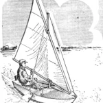 Building a dinghy
Do you want to build a sailboat? Then you'll probably be interested in a dinghy of simplified construction, designed for home manufacturing technology. Of course, while maintaining good...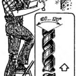 WAS THE DRILL-WAS THE PUNCH
Very often, a broken drill should just throw it away because of the inability to even re-ground it. However, it can be converted into a punch. It is enough to the breaking point to make...
