 Usually when we in the club EN-route modeling at the Tushino syt in the beginning of the school year come the newbies, they are already at the first lesson confides that they want to choose for your first model as a prototype? nail last season Ferrari, the unusual six-wheeled “McLaren” or the unthinkable, PA elegance “Carrera” GT class.
And this is understandable. Collecting car models in 43-m scale has become a craze students. But at some stage the indefatigable nature of boys is not enough purely contemplative or game to do with those little copies of the wonders of engineering, they want to breathe life into their creations. And so they come to us.
On the other hand, we are convinced that the chassis first trace model should be a uniform design (Fig. 2). First, it is easier to organize classes the guys could always minor issues to consult with each other; second, to optimize inventory of materials and tools.
The practice of our mug allowed us to formulate some basic requirements for this chassis: the availability of engine and materials; the lack of turning and a minimum of drilling operations; saving time and effort for parts manufacturing (the Assembly must be provided to fit in place with the max available size).

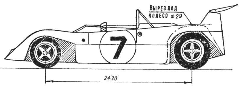
Fig. 1. The body appearance model racing car Mirage M6.
Let’s start with the choice of engine. Perhaps the best known electric motor plant “Norm” nothing will come up. Other low-powered engines, or they quickly fail due to the arcing of a wire brush.
The next important stage — the selection of the reducer. Here we may recall gear that is extracted impatient children’s hands: deformed, flattened teeth. By the way, a thin-walled Cup gear from the toy behaves in the work is very “aggressive” and in a few hours “gnaws” his little . brass partner. We prefer to focus on gear pair attached to the motor “Norma” (it is a spare set). The gear ratio of the cylindrical gear (5:1) close to optimal.
A few words about the layout. The most difficult to place a transversely mounted engine in the case of the model with open wheels. Proposed option the inclined arrangement of the engine not only fits in well with Moody in the layout of the body but also allows you to clip on the magnet body, the seat of the rider. Additionally, there is enough space for the cockpit. In models with closed wheels and engine does not prevent the full study of the parts of the engine.
Due to the fact that the diameter of the driven gear is equal to 28 mm, sometimes you have to sacrifice exact sizes of the rear wheels and make them Ø 29-30 mm, which is 2-3 mm more than the precise scale. However, this increase does not violate the visual proportions of the model.
Instead of complex in the manufacture of wheel rims can be offered the usual (better not blued) clothing button Ø 16 mm. On the wheels they look natural enough. As can be seen from figure 2, other parts are also made from haberdashery and stationery.
The main tool in assembling the soldering iron. It should be noted that the soldering processes children learn very readily.
To start the chassis manufacturer should be the base plate, which is designed to replace the T-shaped protrusions on the magnet cap that existed in the early versions of the engine. Cut out the blank mask, it is necessary to compress directly on the stove so that the last inserted and removed with some interference. Then the base plate without a mask in any way to reliably glue to the lid magnet. Steel knitting needles make two curved beams according to the drawing of the front articulated and carefully solder them to the mask, while trying to ensure their protrusion beyond the mask at 4-5 mm.
From the spokes need to bend the rear frame — first in the form of the letter P, and then bend the “legs” up in accordance with the drawing. It is advisable to ensure the exact distance between the long sides of the half frames is 18 mm, as it relates to security of attachment engine.
Now you can insert the engine side of the mask and to move the rear frame to the joists of the front, making sure that the engine touches the chassis in at least two points.
In the bearing hole of the gear is inserted into a plastic tube. The needle, designed for the rear axle, threaded into the finished bearings, worn gear, and bearings soldered in place, while maintaining the required clearance in the transmission. Clearance can be adjusted slightly by bending the rear part of the half frames.
Finally, without removing the spokes, soldered the coupler when inserted and the motor clamp.
The rear axle is going in the following way. First of all, on the outside of the semicircle of the inner cheeks of the rear wheel of a soft clip buckle carrier, the ends of which are bent at a right angle to the plane perpendicular to the axis.
A nail breaks through the hole under the axle. Led is soldered to the button. Several departing from the end of the spokes, soldered thereto a button 21 (see Fig. 2). Wearing gear, plan holes, which should include all driver, and drill them. Finally fixing the pinion shims are bent or bite off the ends of the carrier. Axle gear inserted into the bearings. Then skewer the restrictive washer and solder it to the axle from the outside. Then soldered the inner cheek of the second wheel, worn tire of sponge rubber and are clamped the outer cheeks. Latest soldered to the axle. The excess ends of the spokes are removed.

Fig. 2. Chassis model (body removed, the driven gear on the side view not shown):
1 — leash (nail Ø 2.5 mm), 2 — insulating bushing (polyethylene tube by the rod of a ballpoint pen), 3 — the lever of the left current collector (tinplate or brass), 4 — front wheel (cushion rubber), 5 — inner cheek of the front wheel (the button for clothes), 6 — pad (soft wire from a paper clip Ø 1 mm), 7 — a current collector (copper wire braid), 8 — panel, 9 — lever with a lug (pin or bent by drawing the wire), 10 — baseplate (Micarta or polystyrene with a thickness of 0.8—1.5 mm), 11 mask (tinplate or brass), 12 — motor “Piko”, 13 — clamp (pin or soft wire), 14 — right base plate (tinplate), 15 — washer-limiter, 16 — bearing (copper tubing), 17 — tie back (needle), an 18 — axle rear (needle Ø 2 mm), 19 — gear driven, 20 — centering bushing (polyethylene tube by the rod of a ballpoint pen) and 21 of the inner cheek of the rear wheel (the button for clothes), 22 — rear wheel (cushion rubber), 23 — the outer cheek of the rear wheel (the button for clothes), 24 — carrier (wire Ø 1 mm), 25 gear presenter, 26 — left base plate, 27.— cross member (needle Ø 1,5— 2,0 mm), 28 — rear of the frame (needle Ø 1,5—2,0 mm) 29 beam front half frames (needle Ø 1,5—2,0 mm), 30 — bushing arm current collector (glass beads), 31 — the axis of the levers of slip rings (wire), 32 — front axle (needle Ø 2 mm), 33 — lever right of the current collector, 34 — spacer-stop, 35 — front bearing (copper tube)
A simple leash model is made from a nail, Ø 2-2. 5 mm, which is soldered between the articulated beams. To frame propitaetsya pad. Between her and the head of the leash is inserted into the bearing of the front axle and soldered in place.
The current collectors are designed with a forced tracking of the profile of the current-carrying bus. Their arms are cut and bent from suitable sheet material. Better if they have the axle bushing. On a round mandrel of the desired diameter bends and prihvatyvaya tin wide end of the lever. You can then insert the bushing (for example, steklorezov bead) and slightly compress the detail. On the mandrel with a diameter equal to the diameter of the tube from a ballpoint pen, it is necessary to bend and grab the narrow end of the workpiece. Each current collector with a welded wire in the cutting tube is inserted into the lever. Into eyes elastic band is inserted, which is put under leash.
If you throw the leash and shorten the beam, leaving the front axle hanging on the strip, then the chassis is easy to combine with conventional T-shaped contact guide site.
The front wheels are attached to the axis in the same way.
As a prototype for copying adopted racing car class In the Mirage M6 (corresponding to the trace class A2). It is necessary to make a 1 : 24 to nature. In connection with the increase of the rear wheels slightly modified, as shown in figure 1, the corresponding side cutout of the enclosure. Along the sides of the case are wooden blocks with holes that it is attached to the chassis.
Neatly done model looks very impressive on the track sleep well, stress, fits well into corners when coasting, confidently takes the ascents and descents is the exit to the turn.
The model is included for team competitions, made a member of the circle trace modeling Tushino syut Sergey Bondarev. For this work young Avtomobilist was awarded the diploma of the laureate of the exhibition scientific and technical creativity of youth in Moscow and the Moscow region in 1976.
I. NIKOLAICHUK


