Floats boat have a classic case design with 3-mm plywood formers and pine stringers with a cross section of 4×4 mm. deck Plating, bottom and sides of the float—1-mm plywood, internal power sidewall from 3-mm plywood. The floats are going on a plane force the sidewalls to him on an epoxy binder are butt glued all the frames are then connected stringers. Ready to frame Marquesa, and it consistently (the bottom—Board—deck) glued sheathing panels. Before gluing the deck, the joints between the bottom and sides are filled with liquid (diluted with acetone) epoxy glue that ensures the integrity of the floats. The same liquid adhesive good handle and the inner surface of the floats — to make the wood water-resistance. At the rear of each of the floats is made airtight hatch: on the right under the steering machine and in the left under the receiver equipment radio control. If the manufacturer of sealed manhole covers meet any difficulties, we can do without it, zakieva holes wide “tape”.
Geometric diagram of RC racing aerolizer with the engine working volume of 2.5 cm^3
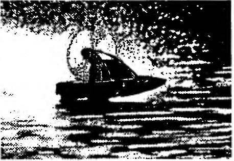
The layout of aerolister:
1 — bridge Central; 2 — spinner; 3 — the screw of the air (d200, h = 150); 4 — engine (KMD-2.5 or MARZ-2,5); 5 — M3 bolt, nut and washer engine mounts (4 sets); 6 — fuel tank capacity 75 ml; 7 — motor; 8 — battery radio control equipment; 9 — cutting Central; 10 — float lateral; 11 —machine steering; 12,14 — pull steering; 13— bracket, steering (duralumin, sheet s2); 15 — feather steering; 16 — hood (AMG or AMC, sheet s1).
Lateral float aerolizer (right hand shown, left — mirrored):
1 — Board transom (plywood s3); 2 — site of attachment of the steering machine (plywood s3); 3 — deck plating (plywood s1); 4,5,7,8,9 — frames (plywood s3); 6 — stringer Board (pine, rail 4×4); 10 — boss bow (Linden); 11 — wall of power (plywood s3); 12 — hull bottom (plywood s1); 13 — bilge stringer (pine, rail 4×4); 14 — stringer zygomatic, rear (pine, rail 4×4); 15 — sheathing seredniy bottom (plywood s1).
Central bridge aerolister:
1 — the boss bow (pine); 2,3 — crossmember front (plywood s4); 4,6,9 — crossmember rear (pine, rail 15×15); 5 — hull bottom (plywood s1); 7 — deck plating (plywood s1); 8 — side plate, outer (plywood s4); 10 — bump feed; 11 —plate side, inner (plywood s4).
Central wheelhouse aerolister:
1 — motor mount (plywood s8), 2 — plate of the engine hood, docking (plywood s4); 3,6,9 — frames (plywood s3); 4 — upper stringers (pine, rail 4×4); 5,10,12 — trim cutting (plywood s1); 7,8 — lower stringers (pine, rail 4×4); 11 — site of fastening of the accumulator battery (plywood s3).
The Central bridge also stacked; it consists of right and left side (each one is glued of two plywood parts), pine cross members and plating of 1 mm plywood. The main problem here is to achieve integrity, which after gluing the bottoms the joints are filled with liquid epoxy. In the manufacture of bridge cross members it is necessary to provide openings, scuppers, and in the back — hole, plugged with a plastic plug. If water will penetrate into the cavity of the bridge through these openings it will be easy to remove.
The Central cabin of the boat is also going out of plywood (thickness 3 mm) frames, pine stringers and plywood (thickness 1 mm) plating. In the back part of the deckhouse is glued motor mount consisting of two symmetrical parts (plywood 8 mm thick). In the Central part of the cutting between the frames is fixed plywood platform designed for the installation of her battery radio. In the rear compartment wheelhouse is welded tinplate fuel tank capacity of 75 ml.
Assembly model special difficulties is not. Thoroughly exposed no Board-the stocks floats are glued together with epoxy resin with a Central bridge, and the latter is mounted a Central control room. It can be installed in two stages; first in the bridge are fixed pine slats with a cross section of 4×4 mm, bent in accordance with the line of conjugation of the wheelhouse and the bridge, and then stick to them actually cutting.
For those modelers who want to “squeeze” out of aerolister all the opportunities incorporated in him, we can recommend this dock floats with the Central bridge, which would allow you to reconfigure the model depending on the capacity and location of the engine, and the condition of the racing area. To do this in a Central bridge secured to two threaded rods of duralumin knitting needles 4 mm in diameter, and the floats are glued thin-walled dural sleeve. Mount floats — nuts M4 washers and rubber gaskets. To rearrange the floats, it is sufficient to Unscrew the nut, remove the bridge from the threaded studs and secure them in the new place. Note that moving the floats forward improves the behavior of aerolister on calm water, and when you shift them back, the model behaves more stable with waves, especially at high speed. However, achieving the optimal position of the floats relative to the Central bridge, you can remove the fasteners and firmly glue the model.
The size of aerolister allow you to install the engines of MARZ-2.5 or KMD-2,5. For these motors quite suitable birch propeller with a diameter of 200 mm and spacing 150 mm, which is a mirror copy of the standard nylon propeller. To compensate for the torque of rotation of the propeller axle of the motor must be shifted to the left (when view from above) approximately two degrees. And to increase longitudinal stability the axis of the screw preferably on the same two degrees to deflect upwards (in lateral view). More precisely, these values should be clarified by the results of the training sessions: when properly installed the engine and when the neutral position of the rudder of the airboat needs to move strictly in a straight line. The engine hood is closed, and villacana cut from 1-mm sheet of AMG or AMC.
The Central bridge is mounted dvuhmetrovoe steering device consisting of a pair of U-shaped steering bracket (aluminum) and two feathers. The latter are collected from the steel steering shaft with a diameter of 3 mm plywood plate with a symmetrical lenticular profile. The shaft is glued with epoxy into a hole drilled in the steering feather. Right and left handlebars are connected through levers and tie bar, forming the likeness of an automotive steering linkage.
I. TEREKHOV, engineer
Recommend to read “BABY” PAVES THE FURROW From the family of microstructures developed by students of Kharkiv Institute of mechanization and electrification of agriculture, the easiest and most accessible for self-production -... THE FARMER’S ASSISTANT The compact universal self-propelled machine MUSM-1 — that's what the young craftsmen from the modeling and construction club of agricultural machines at Novokulinskaya Secondary School in...