
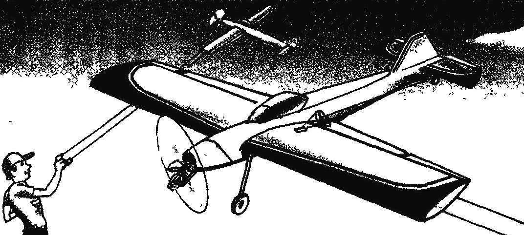
 Control line aerobatic trainer model airplane. In our time, control line model airplanes is significantly different from traditional sports is Now for the creation of models is often taken is not the one who is going to participate in sports, and those who just want to experience the magical feeling of power over the obedient cord pilotami. With considerable help novice modelers have model shops where you can purchase the complete set of elements for Assembly cord models and individual parts and blanks for their manufacture. There are trading firms that distribute their goods by mail.
However, there are still enthusiasts for whom the real pleasure is not only flying models, but also the process of self-construction and workmanship.
We present such enthusiasts simple and very volatile training pilotage under a compression engine with a displacement of 2.5 to 3.5 cm3.
The model is constructed under the scheme low wing with a symmetric profile. When you create a model widely used readily available materials, in particular in the manufacture of many parts were used in various wooden school ruler. In addition, a small number were used balsa and lime harvesting and pine slats.
The fuselage of the model is assembled from wooden plates (school lines with a thickness of 2 mm) pine strips a cross section of 3×3 mm and a plywood of 3 mm thick. note that the width of the lines is generally insufficient for the blank walls of the fuselage, so they have to stick together in pairs using epoxy glue. Besides the thickness, it is desirable to bring to 1.5 mm using a simple adaptation of the electric drill and sanding disc. Frames also are made of lines of thickness 2.5 — 3 mm.
Assembly of the fuselage is the simplest slipway — smooth Board. First going to the top fuselage panel for this wall, carved out of the lineup, contrived pine slats cross-section of 4×4 mm; docking is performed with epoxy glue.
After the adhesive has polymerised, the upper panel is fixed on the Board-stocks, and the panels are fixed to the frames and the tail boss of lime. Next to the frames dock bottom rails (at this stage of Assembly they should be solid from matousek and to the rear of the boss) and beech bars motor a cross section of 6×10 mm. All these elements of the fuselage are connected at the joints with epoxy glue.
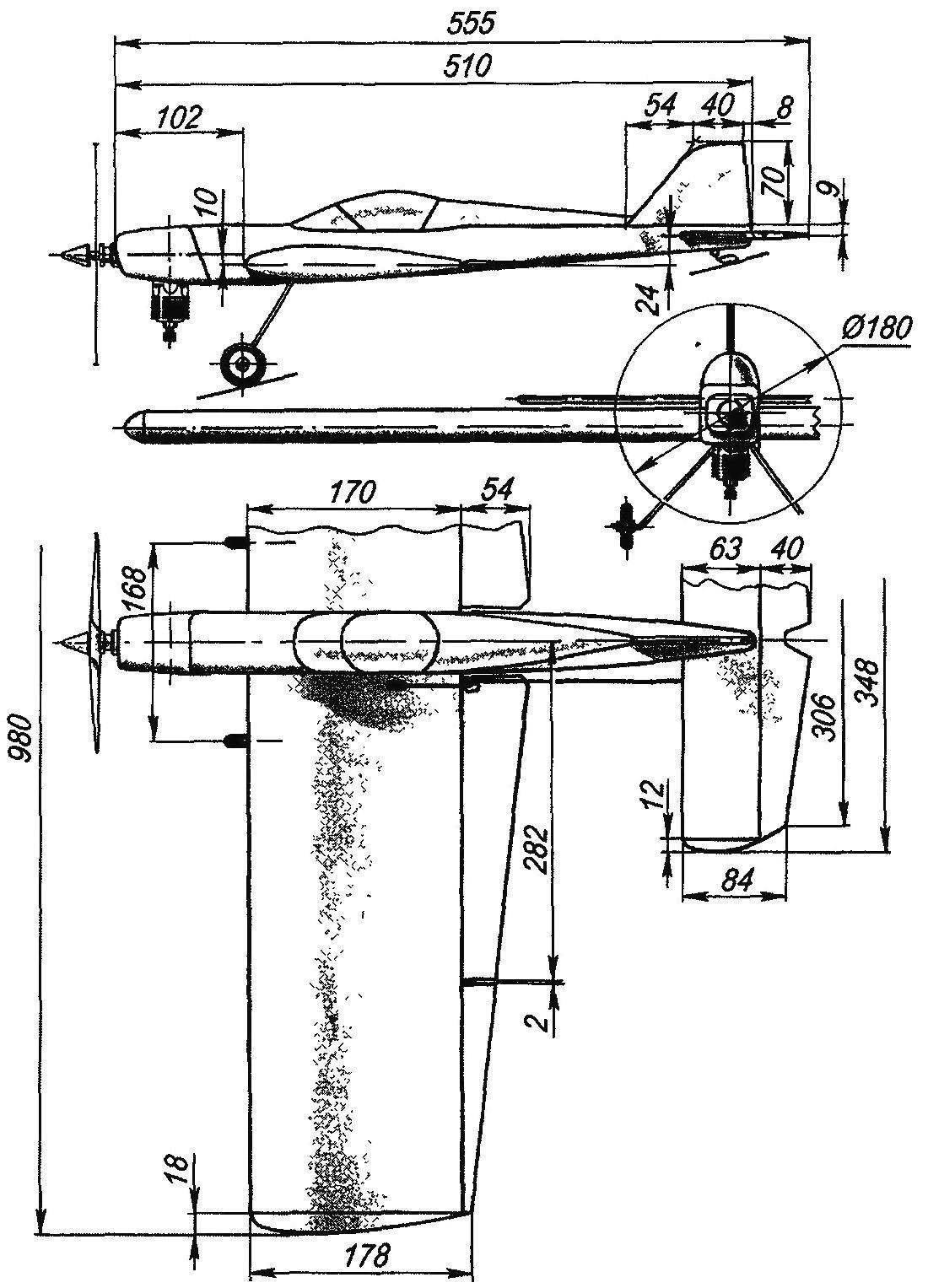
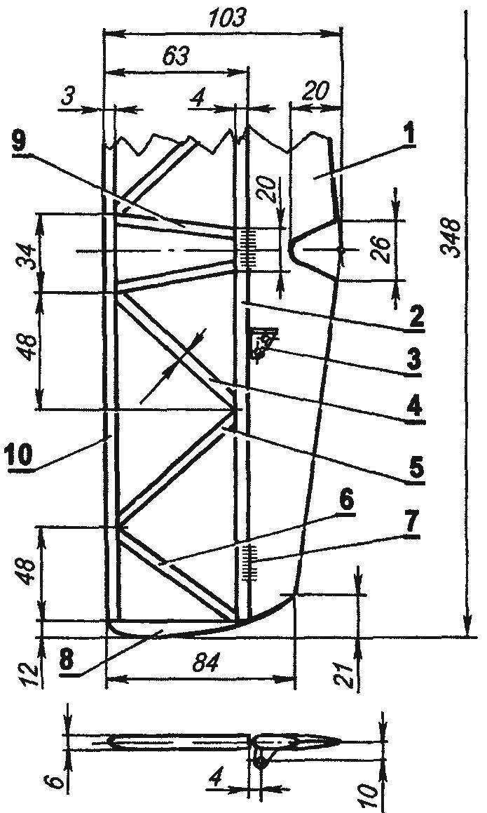
Geometric diagram of the aerobatic training aircraft
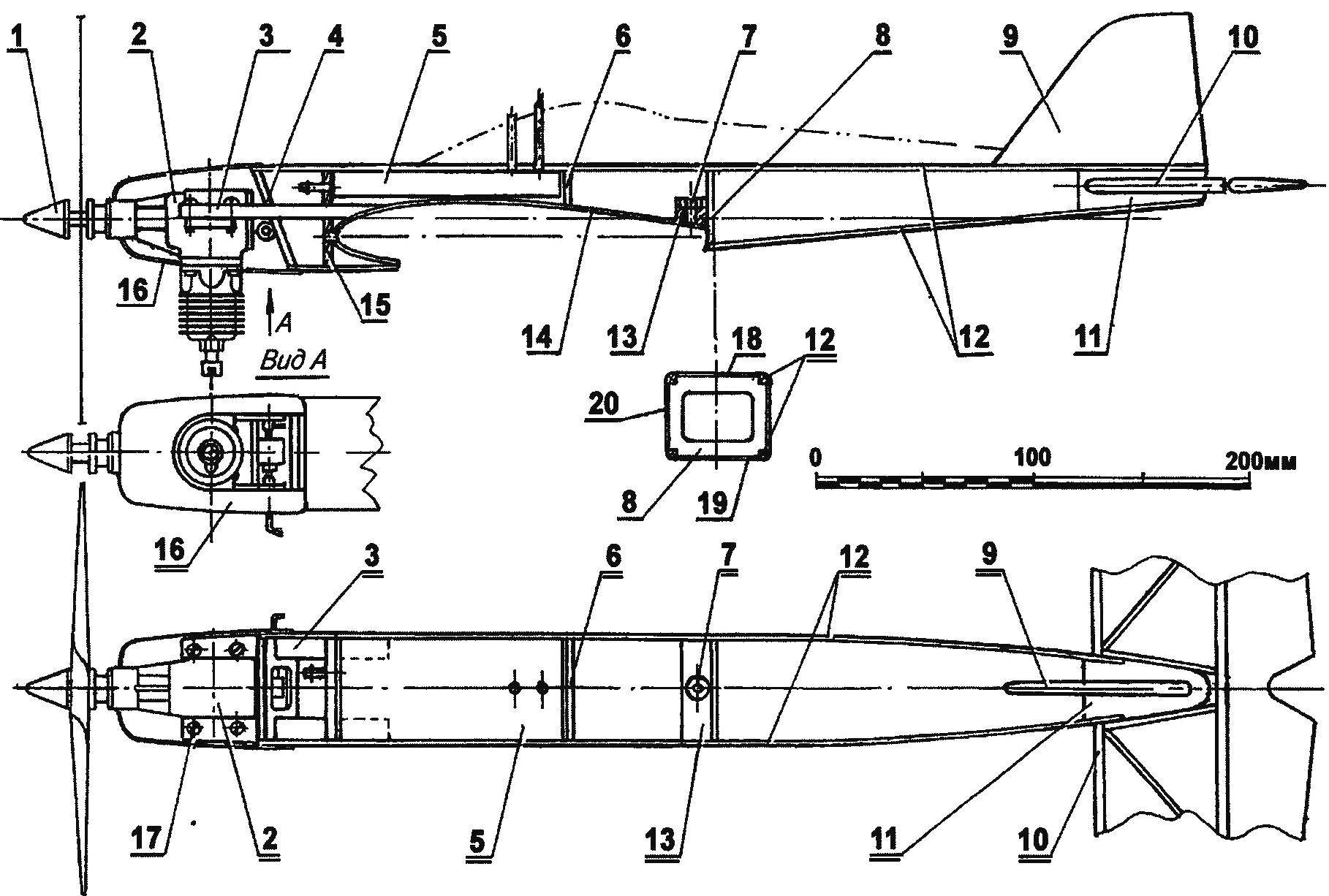
Fuselage:
1 — Kok-nut of the propeller 2, the engine working volume of 2.5 — 3.5 cm3, 3 — motor mount (beech bars 6×10), 4 — frame No. 1 (plywood s4); 5 — fuel tank 6 — frame № 3 (plywood s3), 7 — nut M3 wing mounting, 8 — frame № 4 (plywood s3); 9 — keel (balsa plate s5), 10 — horizontal tail; 11 — caudal boss (Linden), 12 — fuselage spars (pine, rail 4×4); 13 — boss (Linden), 14 — sasukelegend5 under the wing (Linden veneer s1), 15 — frame № 2 (plywood s4), 16 — hood (Vileika of two layers of fiberglass and epoxy resin); 17 — screw M3 and nut of fastening of the engine; 18, upper wall 19, bottom wall 20 and side wall
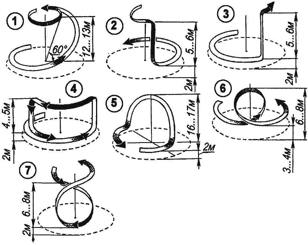
Aerobatics for cord models:
1 — deep bend; 2 — nose; 3 — slide; 4 — “square” loop; 5 — slide diving; 6 — loop the loop; 7 — loopback
Before proceeding to the lining of the fuselage, in the last fuel tank is glued, soldered tinplate with a thickness of 0.3 mm. Tank is a cuboid with a capacity of about 50 ml, to which is soldered a copper tube and filling, drainage and pipe supply. At last the inside of the tank is stretched a flexible silicon tube with a small weight on the end that provides the fuel to be drawn under all evolutions of the model.
After the installation of the tank are adjusted and glued the side and bottom walls of the fuselage.
Next at the bottom and the side walls of the fuselage is cutout under the wing on the frame No. 4 is attached fake boss taped her nut with M4 thread for attaching the wing. After that, the tool tray under the wing is sealed with a fake veneer with a thickness of 1 mm.
Horizontal tail stacked, the frame is glued from Linden slats. After assembling the front edge of the stabilizer kruglitsa, the frame vyshkurivaetsya and fitted by a metalized Mylar film. The Elevator is cut from the balsa plate. After priming and painting it pivotally connects with stabilizer three hinges-“eight mi” of nylon thread.
The finished stabilizer is fixed with epoxy glue in the slot the rear lugs of the fuselage.
Keel — celeberty, after sanding, priming and painting it also attaches in the slots of the rear lugs of the fuselage.
The assembled fuselage is primed and painted with enamel type “Sadolin” is opaque and resistant to fuel the paint has a good Shine to paint better with a spray gun, but a good result is obtained when coating with a foam sponge (this must be pre-probertite, does not dissolve if the sponge used enamel).
The manufacture of the wing it is advisable to start with the preparation of ribs from school lines, 2 mm thick, the front and rear edges and flanges of the spar from pine slats. The ribs are cut with a jigsaw with a small allowance for final machining, which is best done using a simple device. The latter consists of two aluminum templates made in accordance with the profile of the wing, and two threaded studs with nuts. Billet ribs are located between the templates and tightened together by studs and nuts, the package of ribs is processed together so that they work exactly the same.
The rigging is also using the slipway is made of a flat Board attached not her plasim — sheet of paper with the image of her in the frame of the wing full size. The original frame is recorded on the slipway using a paper of pins and sewing pins, and after checking the Assembly accuracy and lack of bias seams are filled with epoxy.
In the middle of the wing are stuck with three fake lugs near the rear edge for the fixing of the wing to the fuselage, in the area of the spar for attachment of the chassis, and the front edge to a connecting pin of beech with a diameter of 6 mm.
The wing surface between the two Central ribs is covered with a fake veneer with a thickness of about 1 mm. From the end rib and the right wing spar between the shelves is fixed by thread and glue a lead weight with a mass of 20 g.
Rocking control is cut from a sheet of aluminum of a thickness of 3 mm, for mounting it in the wing used a box of fake strips glued in between the shelves of the spar. Leashes cord management (they are located inside the wing, between the rocking chair and Konami) Suite from the double-folded steel cords. In the opening leads into the holes in the wing tip there are two springs, wound a coil to a coil of wire with a diameter of 0.3 mm.
In the control system model uses flaps, which during the movement of the Elevator up (stick — on) are deflected down at an angle of about 10 degrees, which improves the handling characteristics of the model and facilitate its landing.
Flaps — seleblitie, each of them after sanding and painting is pivotally attached to the wing loops”eights” of nylon thread. Between the flaps are connected by torsion of a steel wire with a diameter of 1.5 mm.
Chassis model bent wire grade optical fiber with a diameter of 3 mm. Wheels: plastic rubber, with a diameter of about 40 mm and a thickness of about 10 mm — from children’s toys. Fixing wheels on the chassis — inside soldered to the steel rod with washers and outside — the nuts and lock nuts with M3 thread. Mount the chassis to the Central part of the wing is made by aluminum bracket with self-tapping screws.
Wing:
1 — beam flange (pine, raked a cross section of 4×10); 2 — rib (school line s2), 3 — the front edge (pine, raked a cross section of 5×5); 4—filling (balsa plate s5), 5 — trailing edge (pine, raked a cross section 8×13); 6 — ending (Linden), 7 — the guide cords (coil spring steel wire Ø0,3); 8 — covering (Mylar film); 9— pylon control flap (duralumin s1); Of 10.18 — sewing Central part of the wing (Linden, veneer s1); 11,19 — flaps (balsa plate s6), 12 — torsion (steel, wire Ø2 OBC); 13 — control rod flap (aluminum, wire Ø2. 5); 14 — rocking control (duralumin, sheet s3); 15 — box rocking control; 16 —axis rollers (steel, wire Ø3); 17 — remote bushing (PTFE); 20 — hinge”eight”; 21 — connecting pin (beech, Ø6); 22 — front boss (Linden); 23 — the Central boss (Linden); 24— rear boss (Linden)
Horizontal tail:
1 — the Elevator (balsa plate s6); 2 — the rear edge of the stabilizer (lime, lath cross-section 4×6), 3 — pylon rudder (aluminum, sheet s1), 4,5,6,9 — braces (Linden, rail section 3×6), 7 — loop-“eight” (nylon thread); 8 — ending (Linden), 10 — front flange (lime, rake 3×6)
The engine hood wikiepedia of two layers of fiberglass and epoxy resin at a clay disc. After polymerization of the binder harvesting vyshkurivaetsya and covered with enamel. On the fuselage, the cowl is attached with miniature self-tapping screws.
Performance models in General and handling in particular greatly depends on the right alignment — it must coincide with the point corresponding to 20 — 25 percent of the wing chord, measured from leading edge. For fine-tuning the alignment to the optimum, you can use the weight, setting it in the front or the rear of the fuselage.
To start pilotage use steel cords with a diameter of 0.25 — 0.3 mm and a length of not less than 15 meters. Testing of a new model makes sense to produce in calm weather. To run the model you need for two — pilot holds the control stick, and the mechanic starts and adjusts the engine and also holds the model till the start moment, which is produced at the command of the pilot.
The model takes off, usually after a run in 2 — 3 meters. Next, the pilot should be a slight movement of the control knob “on” (this is movement of the entire hand, not brush) to raise pilotage to a height of about 2 metres and to manage the model in horizontal flight. And only after that you can go to the simplest maneuvers — slides, turns and dive, and then to the more complicated shapes — classic and square loops and eights.
I. SOROKIN
Recommend to read
 “PERPETUUM…CLOCKS”
Those who use kettlebell wall clock-hodinami know" that when lifting weights hang down with chain often broken original position of the case, affecting their accuracy. To avoid this, I... FERRARI 612 SCAGLIETTI
The debut of this most powerful and most expensive car that produces the famous Italian firm, was held in January 2004 at the prestigious Detroit motor show. The machine will replace...
