To begin work on the preparation of the model suggest of the fuselage. The nose part is cut from high quality 12 mm plywood, the Central is a flat farm, a laminated cedar top and bottom contours of slats section 12×7 mm, internal bracing — strips of a cross section of 10×4 mm. on Top of the struts are mounted, the stringers of the cubes cross-section of 4×4 mm. Assembly of the fuselage is carried out by using epoxy glue.
After curing of the binder in the Central part of the fuselage zashlifovyvayutsya — wedge thickness is 12 mm in the area of the wing and 4 mm for the keel, and the tail section are glued plate made of plywood with a thickness of 1.2 mm with a groove under the stabilizer. Next on the forward fuselage glued the lining of 3 mm plywood to the right with the groove under the engine and left without a groove. Motor mount is done from a pair of birch sticks thus ensuring that Vegas engine — three degrees in the outer (portion of circle) side.
Strut Assembly:
1 — brace (birch, 8×6 rail); 2 — site of attachment of the brace (made of anodized aluminum, sheet s2)
Simulation of the lamp is a plate of organic glass thickness of 4 mm. For fixing it in the forward fuselage at the seam hollows out a groove width and a depth of 4 mm, and at the bottom of the “lantern” nastelivaetsya horizontal holes with a diameter of 2 mm for glue, after which the plate is inserted into the groove of the fuselage and fixed it with epoxy glue. You should warn young designers that the lamp should be replaced only after pre-Assembly of the model and verify its symmetry and regularity of arrangement of the wing and struts
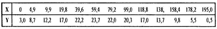
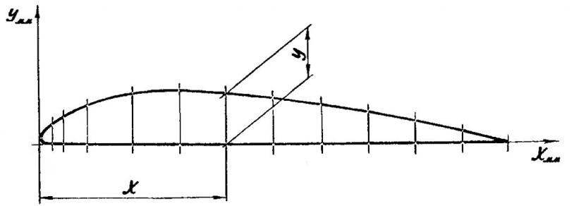
The wing model has a PLANO-convex profile with a relative thickness of 12%. Spars from pine slats with a cross-section 8×4 mm, front edge — lime block, cross section of 6×6 mm, back edge — the cedar rail section 10×5 mm. Ribs cut out of plywood with a thickness of 1.2 mm, the location of the ribs along the span of the wing corresponds to their location on the plane prototype. The root rib consoles — cedar, 8 mm thick, lined on the outside of the plywood plate with thickness of 1.2 mm without cut-edges and spars. Wingtips is laminated on the mandrel plywood of seven layers of spruce veneer in the thickness of 0.8 mm using epoxy resin. Console attached to “the lantern” a pair of threaded studs M4 with nuts and washers, which in the root rib and “light” holes are drilled with a diameter of 4 mm.
The struts are made of birch slats 8×6 mm oval section; the attachment — pasted on the epoxy into the slots in the braces of strips of 2 mm thick duralumin. mounting Brackets to the wing struts are cut from 2-mm sheet of aluminum; the spars are fastened with bolts with thread M2. Brackets-angles of attachment of the struts to the fuselage is carved from a corresponding aluminum profile with flange thickness of 2 mm to the fuselage they also are fastened with bolts with thread M2 with nuts and washers.
The keel, rudder, stabilizer and elevators — matched, made of cedar. The trailing edge of the stabilizer, the leading edge of the Elevator and rudder, as well as the contour of the keel from the Reiki section 10×5 mm; cross-set tail — bars cross-section of 5×5 mm. the Rudder is mounted on the tail with pins of mild steel wire (from an ordinary paper clip) — this allows you to change the angle of deflection at the test flights of the model. Halves of the Elevator are connected with a torsion bar of hard steel wire, allied with a diameter of 2 mm. Loop of mounting the elevators are made of fishing line 0.15 mm in diameter, braided on the stabilizer and rudders “eight”.
The main landing gear cut and bent sheet of aluminum with a thickness of 2 mm. To the fuselage they are mounted a pair of MZ bolts with nuts and washers. Wheels with a diameter of 50 mm — type “Thermals”, axis — threaded rods MH, mount wheels with nuts and locking their nitro Tail wheel plastic, with a diameter of 20 mm; the front of the wire type, allied with a diameter of 1.5 mm is fixed in the fuselage with epoxy glue. The wheel is fixed on the front soldered to it a metal washer.
Control system — standard for cord models of this type. Control rod connecting the rocker with the horn of the Elevator is a round pine rail with a diameter of 6 mm with a wire okoncovke with a diameter of 1.5 mm. the mounting bracket of the rocking — dural “area” with a wall thickness of 2 mm; the fuselage it is attached with M4 bolts with nuts and washers. The rocking chair — sheet duralumin of a thickness of 3 mm.
The fuel tank model with a capacity of about 60 ml — tin, soldered to the fuselage it is attached with two screws-sa-moresome with a diameter of 3 mm.
The finish is fining her macalintal paper on Amalia and colouring by nitroenamels in accordance with the color of the prototype aircraft.
I must say that the model turned out to be surprisingly strong. One of twelve copies are made by us after fifty flights, we removed the trim and checked all the glue joints the strength of the structure as a whole. As it turned out, the frame had no cracks, no broken glue joints.
Vladimir KOZIN, head of the aeromodelling circle, Magadan
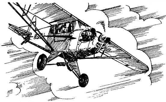
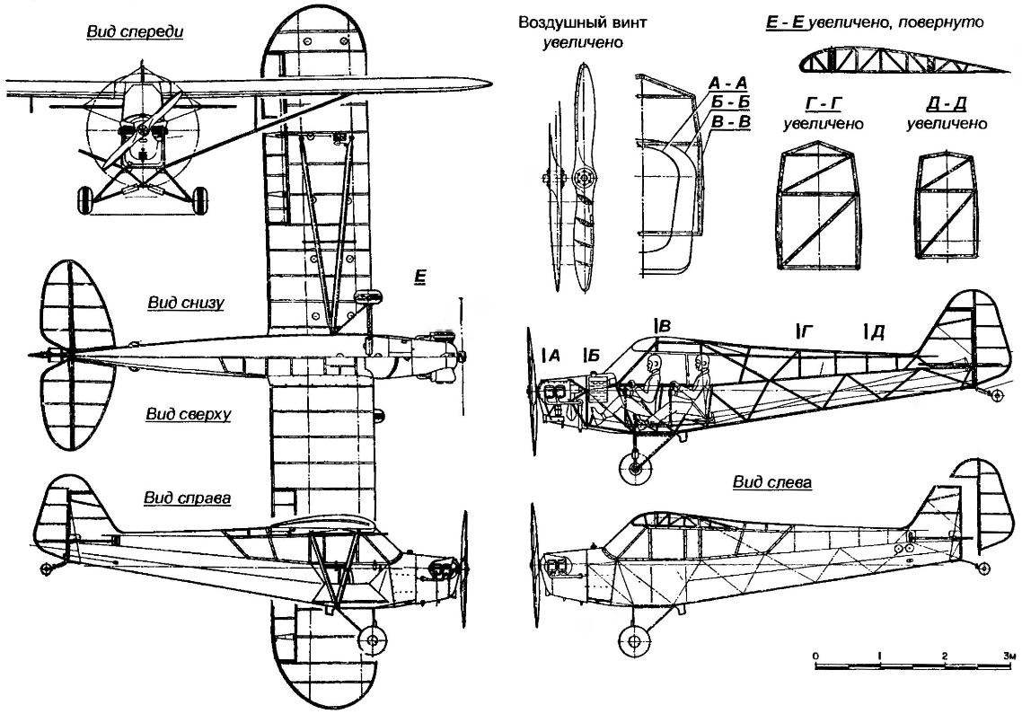
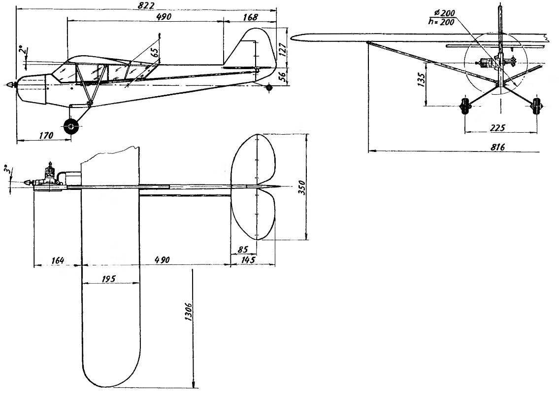
 Competitions of different rank showed that as prototypes for the manufacture of contour models are used only a dozen types of aircraft. And to participate our aeromodelling circle in the next competition, it was decided to make a model rare prototype. Our choice fell on PIPER CAB, one of the most successful light aircraft, produced in mass quantities since the pre-war (1935).