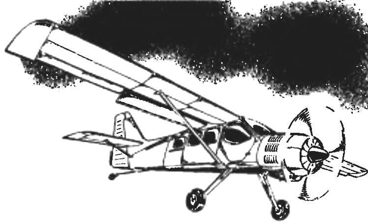
 The creation of RC model aircraft preceded, as a rule, the search of the prototype aircraft, because aviation hobby in the first place, is a small picture of the real aircraft. As for the “Finist”, selected as a sample when designing a radio-controlled model, he seemed to be specially created by the designer as a future prototype flying polyopia. In favor of this choice — and the wing of large aspect ratio, and developed a stabilizer, and a rather large keel, and a voluminous fuselage, makes it easy to install control equipment model.
A little about the aircraft prototype. Finist developed in the early 90-ies of the last century, a light aircraft designer Vyacheslav Kondratyev, known for his participation in the design of sports acrobatic “Jacob” and “su”.
Finist was created by V. Kondratyev as light multipurpose aircraft that can be used at least ten different options. Including passenger— to transport five or six passengers with Luggage; transport to deliver cargo weighing up to 600 kg; the patrol for surveillance of forests, power lines, pipelines; aerial — photographic equipment weighing up to 600 kg; airborne — parachutist training or dropping parachutists-firemen with equipment; search and rescue; health; agriculture and training.
Finist is an all-metal aircraft with piston engines air cooled M-14N output of 360 HP with direct injection system, electronic control and electronic ignition. The power plant has a three-bladed propeller pitch is automatically created together with the German firm “Muhlbauer”.
The aircraft can be operated on any elementary prepared sites with low strength of the soil that is provided with a spring main landing gear and the sprung tail wheel. The aircraft can be equipped with wheel-ski landing gear or floats.

The light multirole aircraft SM-92 “Finist”

The geometric scheme of the RC model “Finist-RC”

The layout of the model:
1 — propeller (Ø270, h=130); 2 — hood (Vileika fiberglass); 3 — engine “rainbow-7” or O. S. MAX-40LA; 4 — sub frame (D16T); 5 — muffler; 6 — the Central rack (pine); 7 — windshield glass (Vileika from glass); 8 — wing; 9 — servo control of ailerons; 10 — steering the machine, the throttle of the engine; 11 — torsion actuator Aileron (steel, wire Ø2 OBC); 12 — trim the top of the fuselage (balsa s3); 13 — frame № 4 (balsa s3); 14 — dorsal fin (balsa s6); 15 — frame № 5 (balsa s3); 16 — keel (balsa s6); 17 — the rudder (balsa s4); 18 — hog of the Elevator; 19 — boss (balsa); 20 tail driven bearing; 21 — tail wheel; 22 — horizontal tail (balsa s6); 23 — the Elevator (balsa s4); 24 is the sidewall of the fuselage (balsa s5); 25 —sheathing the lower part of the fuselage (plywood s1); 26 — frame № 3 (plywood s3); 27 — Aileron (balsa s6); 28 — steering car steering-height; 29 — steering machine steering direction; 30 — M4 screws mounting spring suspension; 31 — wheel chassis; 32 — spring chassis (duralumin D16T, sheet s4); 33 — fuel tank (plastic bottle); 34 — frame № 2 (plywood s3); 35 — spring base chassis (“sandwich” of two layers of 1 mm plywood and two layers of 3-mm plywood); 36 — Klondike (“sandwich” of two layers of 1 mm plywood and two layers of 3-mm plywood); 37 — M4 screw mounting wing; 38 — hog steering direction

Wing:
1 — the leading edge (balsa 30×6); 2 — trailing edge (balsa 12×6); 3 — strengthening the trailing edge (balsa 15×3); 4 — shelf side member (pine, rail 6×6); 5 — Polonnaruwa (balsa s3); 6 — hinge suspension of the Aileron; 7 — rib (balsa s3); 8 end rib (balsa s5); 9 — ending (balsa s3); 10 — solitaire (balsa s3); 11,12 — the lining of the wing (plywood s1); 13 — insert (beech, rake 15×12); 14 — the wall of the spar (balsa s3); 15 — Aileron (balsa s6)
The table control section of the wing profile (P-II-14%)

The crew consists of one pilot. In the training version of the aircraft has a paired control.
Finist: wingspan 14 600 mm, the length of the plane 9130 mm, curb weight of the aircraft 1350 kg, normal takeoff weight of 1950 kg, the crew of 1 person, range with maximum fuel reserve of 1000 km, the maximum horizontal flight speed of 290 km/h cruising altitude up to 3000 m, required runway length of 400 m.
RC model engine working volume of 6.5—7 cm3 was designed basically in accordance with the parameters of the plane-analogue, but it took some adjustments of the model geometry. So, the increased width of the wing, the ailerons occupied the whole of its range, acquired a fuselage rectangular in cross-section form. Finist, however, remained quite recognizable, and its aerodynamic configuration changes just won.
Model “Finist” were surprisingly technologically advanced. Of course, if you do it from balsa wood — material, though expensive, but now quite affordable. From such timber, almost all the details of the wing and fuselage can be made razor-sharp knife with minimal use of the jigsaw.
To start work it is most convenient from the wing. Unlike the prototype of the wing has no angle “V” is simpler and easier. Wing design is quite traditional, unusual only its front edge. Before you start preparing the details of the wing should be on the following table to cut the profile template, which will be monitored by the manufacturer of the balsa ribs.
By the way, for the model selected, 14% profile of R-II with high load-bearing characteristics, including at high angles of attack.
A few words about the technology wing Assembly. The frame is composed of ribs, edges and flanges of the spar, is going with the use of pins on the Board-the slipway, after which all the joints are filled with epoxy. After curing of the binder adjusted the panels sewing the center section and the frame are pasted all remaining details. The wing is fitted by a Mylar film red or blue (the colors of the prototype aircraft) using glue BF-6 and electric iron. When attaching the wing to the fuselage, you must ensure proper installation angle for building horizontal fuselage, equal to zero degrees.
The ailerons seleblitie suspended from the wing hinges such as “thermals”. Drive each Aileron with the help of the torsion bar, bent steel wire, allied with a diameter of 2 mm. the Angle of deflection of each Aileron from neutral to 15 degrees.

Main chassis:
1 — spring (D16T, sheet s4); 2 — wheel; 3 — M4 bolt with bushing and nut

Tail wheel:
1 — body (duralumin, s1); 2 — drive driven wheel (rubber ring), 3 — rudder model; 4 — hook; 5 — washer (soldered to the fork); 6 — aluminum rivet Ø2; 7 — bushing (plastic tube); 8 — fork (steel, wire EOD Ø3); 9 — wheel
The fuselage of the model is quite simple structurally and technologically in the manufacture and Assembly. Its power base — the balsa sides with a thickness of 5 mm; covering the upper part of the fuselage with 3mm balsa, the lower 1 mm plywood. Frame No. 1 (badmotor-NY) is a “sandwich” of plywood (thickness 3 mm) core, laminated with two sides of 1 mm on plywood frames No. 2 and No. 3 (under-wing) cut from 3mm plywood and the rest from 3mm balsa. In the rear part of the fuselage glued balsa boss.
The fuselage is going on first pins, which allows the maximum precision to combine mating parts. To give the rear fuselage curved forms are used with suitable wooden racks and contractible rubber strap. If the Assembly technique will not allow you to assemble a symmetrical fuselage (it requires some skill), it makes sense to make the simple staple flat Board with notches on its narrow side, in which tiny wedges are fixed to the frames. With this arrangement, the frames can be thoroughly checked in accordance with the drawing, and then to correlate them with the sidewalls of the fuselage.
Further, all the joints of the Assembly element is filled with epoxy glue, and after its polymerization in the fuselage fixed fee servos, scarves with threaded bushings-fungi wing mounting, bar mounting springs chassis glued to it six bushings-fungi with M4 thread, lodgements fuel tank mounting, bodini control rods and other stuff. Only after that the fuselage is sutured completely.
Keel — celeberty, is cut from a plate thickness of 6 mm balsa and cut the dorsal fin, and rudder. The last is hung on hinges such as “thermals”. Stabilizer and Elevator also seleblitie. The stabilizer is fixed in the cut made in Kiel. Halves of the Elevator are connected by a torsion wire, allied with a diameter of 1.5 mm. the Installation angle of the stabilizer is zero. The deviation angles of the rudder pitch and direction — 20 degrees from neutral.
The fuel tank is made of a suitable plastic pharmacy bottle. You should only can see whether it does not dissolve components of the fuel mixture. Mount the fuel tank to the cradle mounted on the frame № 2 — the rubber strap.
When installed on the engine model “rainbow-7” makes sense to equip it with a propeller with a diameter of 270 mm and a step of 130 mm.
The engine hood wikiepedia of fiberglass and epoxy on the foam, puttied up the clay disc. You can also beat the hood out of sheet aluminum brand AMG. The use of thermoplastic materials type of Plexiglas or polystyrene undesirable heating of the engine is large enough, which can lead to deformation of the part from these materials.
Servos that control the Elevator, rudder and throttle of the carburetor, mounted on a common circuit Board with 3 mm plywood servo control of ailerons attached to the wing center section.

The basic chassis spring type fixed on the model with six M4 screws. Spring — dural, is cut from a sheet thickness of 4 mm; its width at the fuselage is 36 mm, the wheels is 15 mm.
Tail wheel driven. Plug chassis — wire OVS with a diameter of 2.5 mm. the Base of the fork is bent from sheet aluminum with a thickness of 1 mm. Prior to Assembly on the plug is worn cut along the plastic tube — the rod of gel pens. Tail wheel is going to use aluminum rivets. The drive managed wheel rubber ring connecting the leash wire landing gear with a hook on the rudder.
Alignment of the model is about 20 percent chord of the wing.
I. ZHUKOV


