REZINOMOTORNAYA, CONTOUR

REZINOMOTORNAYA, CONTOURUsually, it often happens that the outwardly unprepossessing models-silhouettes start your journey in technical sports boys. After one or two procopii, they are taking with them part in her first competition and… don’t remember about contour, as we approach a much more sophisticated technique. Therefore, it is rare silhouette microcodable worthy of attention: because most often they come out from under too inept students.
But the appearance and contour of the model, and its driving characteristics largely depend on fabrication technology. Typically, the basic material used plywood medium thickness. Namely with her, and are associated main problems: the main tool of processing of the contours of the jig — saw, contact with which on “you” guys learn how only a couple of years. So now, when it is not so difficult to provide a circle of foams of good quality can be recommended to move away from traditional technology and use of the foam. Of preparatory operations should be undertaken only cutting boards on “Board” with a thickness of about 5 mm and polishing their surfaces.
 
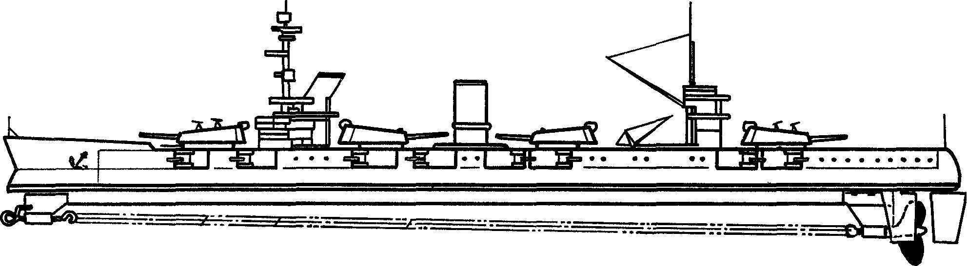
It should be noted that the cutting contour of the ships of these billets becomes a pleasure with very good directional tool — polished knife with a sharp narrow blade. But the results are higher than those of plywood. Moreover, the foam — material pliable, and a little know how boys manage to make of the individual parts add-ins, tubes and towers. Even beginners can offer such a complex and seemingly busy copies, one of which is as an example shown in the figure.
Fig. 1. A contour model of the ship.
Fig. 1. A contour model of the ship:
1 — bow bracket rubber motor, 2 — hook with the curved retaining feature when moving forward to have a rubber tourniquet, use a drill directly on the model 3 — the wiring of the rubber motor, 4 — power beam engine, 5 — horizontal plate-circuit (“top view”) housing, 6 — contour image of the topside of the ship, 7 — rear bracket rubber motor, 8 — the side-wheel, 9 — the main Central wheel, 10 — wood insert for mounting the wheel and bracket, 11 — trim plate-contour “top view”, 12 — foam part 13 — bow insert for the mounting bracket.
 
Fig. 2. The bow bracket with a hook of the rubber motor.
 
Fig. 3. The rear bracket with the propeller shaft and modified industrial plastic propeller.
 
Fig. 4. Homemade thruster of the new type. When assembling the parts to solder together, wrapped the shanks of the blades a thin bare copper wire.
 
Fig. 5. Standard design the helm.
Fig. 5. Standard design steering wheel.
 
Drawing on the bare foam is better not to move: a drawing made on thin paper or tracing paper is fixed on the workpiece in several places on the “points” of PVA glue outside of the working area. Cutting is conducted along with a paper detailing drafting drawing. The outer surface of the silhouette after Stripping of the contour in the right places podsalivaya and is painted with oil enamels. In this way it is easy to make and “top view”. However, before painting it is useful to turn over fake veneer, sliced into strips of appropriate width.
This technique gives results on the mass of the “body”, providing a high speed model. The power part of “housing” becomes a wooden rail extending from the bottom and simultaneously performs the functions of the keel fin, stabilizing microcodable on the course. And in order to eliminate the influence of the powerful torque of the rubber motor, it is useful to equip the system with a copy of the rudders. It includes a well-developed Central plane to compensate for torque and two additional, for course correction. Compensation wheel is in the area of the jet propeller, and undercarriage wheels — on the sides of the drive screw.
 
In conclusion — on-rotor group model. This site deserves special attention, as it mainly depends on the distance and speed polyopia. In most cases on modern contour models use two types of propellers: a tin of homemade and industrial plastic kits for modelers. Second… they are difficult to tell, since even after the removal of the dross from the casting screw remains the product that need improvement, which is not able to perform even high school students. Moreover, the fin size other times the blade thickness the three blades after Stripping varies more than three times!
 
Not too favorable and classic tin screws. The fact is that because of the technology of production (from single patterns) on the screw in the center is formed a developed zone, which is only able to slow down the movement of the model. The situation is, to put it mildly, weird: the ends of the propeller pulling forward, and the center brakes. From these shortcomings spared the propeller is new, as shown in figure design. It should be noted that in this way it is possible to make not only dwuhlopastny, but “propeller” with a large number of blades. After Assembly tin parts are twisted to produce approximately equal pitch at all radii of the screw.
 
A. ALEKSEEV, engineer, group leader

Recommend to read

  • STOOL-TRANSFORMERSTOOL-TRANSFORMER
    This versatile stool which if necessary can turn into a small stable ladder, absolutely necessary in those apartments where there are high cabinets and mezzanines. To produce such a...
  • “BEAVERS” AND “SEALS” THE KRIEGSMARINE“BEAVERS” AND “SEALS” THE KRIEGSMARINE
    The German Navy was engaged in an ultra-small boats only in 1944. Prior to this the Germans managed to capture a number of European States, without resorting to the use of underwater...