SPINNING TOP ON A ROPE

GYROSCOPE ON A ROPEYou never thought about the fact that your car racing has a good gyro, and not one? But they are made and put into place your own hands! Their role is carried out by the engine flywheel and gear wheels. In the not-so-small mass and size, the frequency of their rotation is so large that such is not always seen in the “adult” technique.

The gyroscopic effect, which characterizes the desire of a rapidly rotating mass to keep its position in space, fully manifested in the races of micromachines on track. How? Let’s try to understand. First of all, agree that the moment the front wheels on the behavior of the model can be neglected — they have compared to back minor mass and smaller diameter.
 
After preliminary transformations of the obtained formula to determine the gyroscopic moment in the conditions (the radius of movement of the micro-car, only according to the rules of the competition is equal to 995 cm):
 
M = 14,89·10-7·P·R2·n·V (g·cm),
 
where
P – the weight of the flywheel or wheel, g,
R is the radius of the flywheel or the wheels, cm,
n – frequency of rotation of the flywheel or the wheels rpm
V – model speed, km/h.
 
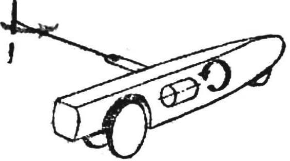
When analyzing influence on the behavior of the model the gyroscopic moment of the flywheel can be considered the four possible cases: 1 — the model moves counter-clockwise motor rotates counterclockwise 2 — model moves in a clockwise direction, the motor rotates counterclockwise, 3 — model moves counterclockwise, the motor rotates clockwise, the 4 — model moves in a clockwise direction, the motor rotates clockwise.
In the first and fourth cases, the gyroscopic moment of the flywheel pushes the front wheels and lifts the rear of the track, the second and the third effect is the opposite.
 
Analyze the effect of gyroscopic moment of the wheels showed that in all cases this point is trying to tilt the model towards the periphery of the Assembly.
 
Fig. 1. Possible combinations of directions of motion of the model and the rotation of the flywheel
 
Fig. 1. Possible combinations of directions of motion of the model and the rotation of the flywheel
 
Fig. 2. Graphs of the gyroscopic moment M of the radius, weight, frequency of rotation of the flywheel and the speed of motion of the model.
 
Fig. 2. Graphs of the gyroscopic moment M of the radius, weight, frequency of rotation of the flywheel and the speed of motion of the model.
 
Let us for example consider how important the above factors. The calculations give the following results: the magnitude of the gyroscopic moment of a flywheel weighing 100 g with a radius of 1.6 cm at a speed of 30 thousand rpm and the speed of the model 260 km/h is equal to 2970 g, see For wheels weighing 60 grams, having a radius of 4 cm and rotating at a rate of 20 thousand Rev/min, 7430, g, see
 
It would clearly be a mistake to consider these values or ignore them! In fact, besides the redistribution of load on front and rear axle and tilt the model to the outside, these moments manage to expand the micro-car, only while it was departing from the track at the jump. The subsequent alignment resulting in loss of speed.
Similar dependencies are obtained for determining the influence of gyroscopic moment of the rotating wheels. As he tries to overturn the model to the periphery of the Assembly, it is advisable to compensate for the time shift bar cord on the value h defined by the parameters of the model and its motion. In this case, under h, P, R, V, n little micro-car will be in a vertical position. The required offset can be quite small, but it is necessary to take into account it. The fact that the cord strap in a vertical plane is not perfectly rigid, and substantial uncompensated gyroscopic moment will cause its deformation and hence, significantly tilt the model. The deformation of this measure for speeding in a circle at a speed of several hundred kilometers per hour, “the shell” is extremely difficult, and therefore more useful to take a pencil and calculate necessary adjustments.
 
Fig. 3. The correction of the position of cord strap height and movement of the model when in standard plank position, b — position with adjusted straps.
 
Fig. 3. The correction of the position of cord strap height:
 
a — movement of the model when in standard plank position, b — in adjusted position strap.
 
The influence of the rotating elements on the engine at the rate of can be neglected. Length of cord strap and its stiffness in the horizontal plane is quite large and the tension on the cords is many tens of kilograms. Therefore, the maximum adjustment position of the strap along the length of the little micro-car would not exceed 1.0 mm.
 
Try to consider factors with whom you met, when designing the new model.
 
A. ERMAK, A. MAZAKAS, engineers, Leningrad

Recommend to read

  • SNOWMOBILE: IDEAS AND DESIGNSSNOWMOBILE: IDEAS AND DESIGNS
    Interest in snowmobiles as individual means of transportation on winter roads and sporty type motor vehicles manifested itself long ago. But as widespread as it is now, the hobby of...
  • “THIRD HAND” TWEEZERS“THIRD HAND” TWEEZERS
    Hams know how sometimes when soldering they do not have a third hand to fix a small detail. At the time it was proposed many devices that can help in such a situation (see, for example,...