
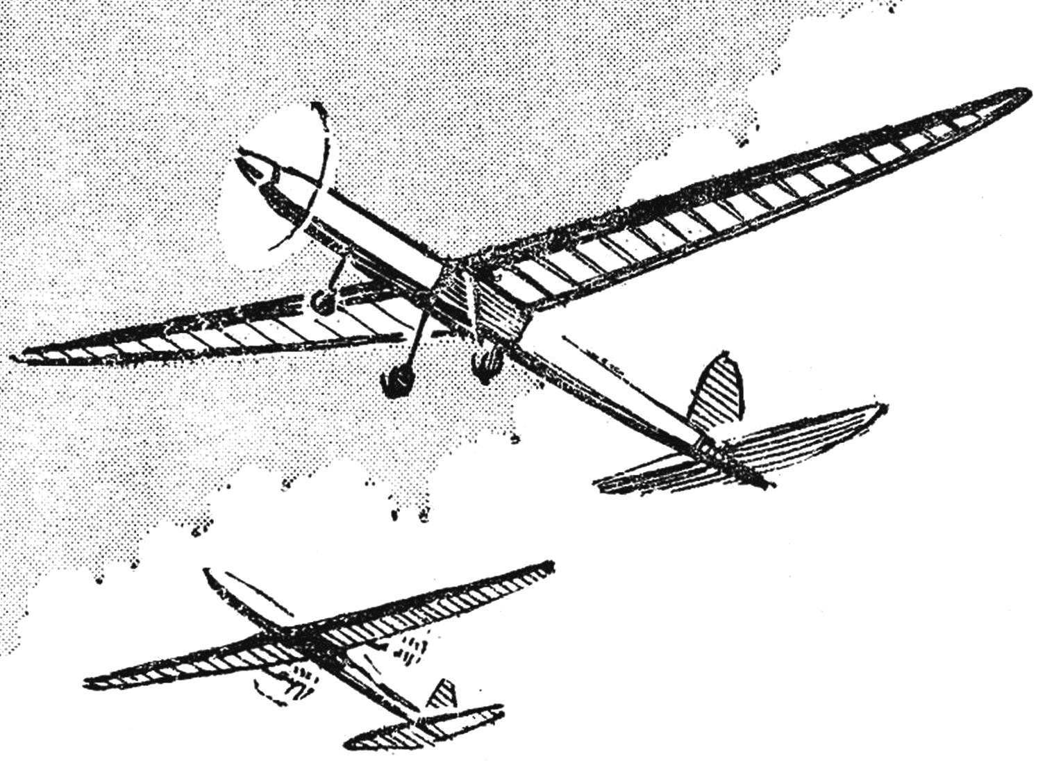
 Flying model aircraft with electric motor is silent and doesn’t poison the atmosphere with exhaust gases. Model spared from the shaking characteristic of internal combustion engines, and, consequently, radio equipment, installed on the models with a motor, works more reliably (especially servos). That’s why recent sales microelectronical new grades immediately attracted the attention of modelers. However, the first samples have revealed some of their weaknesses: the unreliability of the brush mechanism and bearings, lack of ventilation of the armature and ferrite-barievykh magnets. Used for the manufacture of parts of the armature and commutator polystyrene cannot withstand high temperatures (150-170°).
What can be done to “cure” these generally promising, the motors and apply them in flying models?
One of the oldest Soviet modelers, Sergei Mikhailovich Podgorska, who has long been involved in issues electroplate.
It’s safe to say that the remake of most mass Soviet microelectrophoresis DI-1-3 and MED-40 will allow to create not only a great flying kordovye, but models of free flight (the latter in complex with a light and powerful power sources battery type SP and 1.5).
To increase the reliability of the engine, you need to perform the following work: replace wire brushes collector coal or copper-graphite, drill ventilation holes in the housing of microelectrodes and back cover rewinding the anchor with a thicker wire, to replace not withstand heat back cover with brush-like device to put a new axle and manifold (on the motor, DI-1-3 should put the manifold from the engine der-40). To execute the above work the engine should be completely disassembled to remove the plastic housing cover by prying a thin screwdriver metal legs, carefully remove the armature and magnets, pre-marking the right and left, and in the metal engine block carefully drill vertical holes of Ø 4 mm in accordance with figure 1.
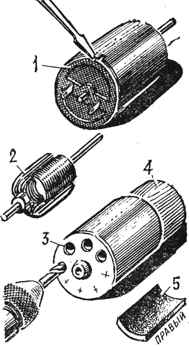
Fig. 1. Disassembly microelectrodes D-1-3:
1 — removal of branded plastic cover, 2 — the anchor is removed from the coil, header and axle, 3 — drilling holes Ø 4.5 mm in the front of the engine, on a wooden mandrel, 4 mandrel 5 is removed from the housing the magnet.
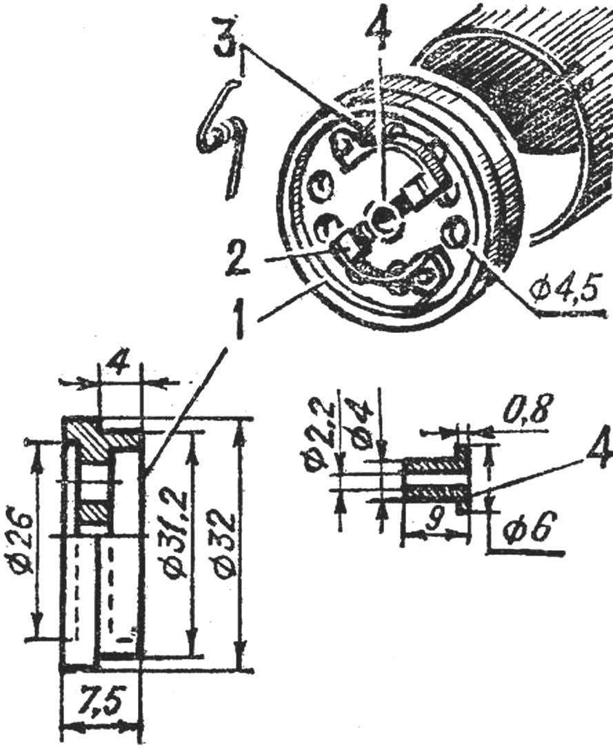
Fig. 2. Manufacturer new cover from Plexiglas and the placement of the brush holders:
1 — cover, 2 — brush holder 3 — brush holder spring, 4 — bronze bushing of the rotor shaft.
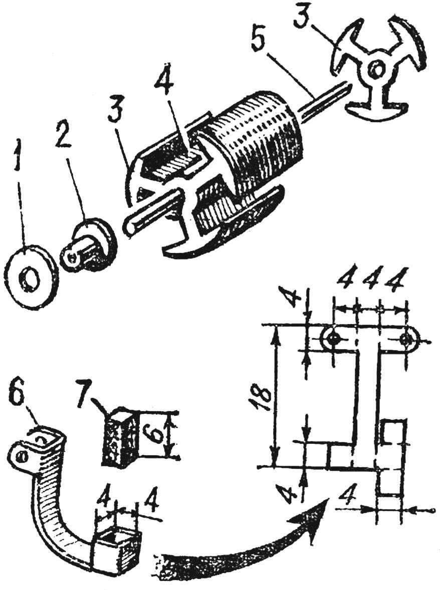
Fig. 3. Modification of the armature and manufacturer of brush holder:
1 — pressure washer manifold (GRP), a 2 — manifold body (ebonite), 3 — insulating cheek anchors, 4 — anchor, 5 — axis armature (steel needle Ø 2 mm) 6 — scan the brush holder (brass, thickness 0.7 mm), 7 — carbon brush.
In refining the body of the motor, DI-1-3 edition, 1977, so as not to damage fragile parts during drilling, should be tightly inserted into the case round the edge. The holes in the back cover are drilled the same way, but before drilling removable brush.
Instead of the regular cover enclosures need to carve new, more heat-resistant material (e.g., Plexiglas), and mount the new brush mechanism (Fig. 2). To make the brush holder (Fig. 3) require a tiny instrument: small hour-pliers, small hammer, weighing 40-50 g, a set of needle files and a good table Vice. Soldering cannot be used. Themselves brushes can be cut from charcoal to electric shavers.
Rewind anchor — the most difficult operation. First, cut the old coil (insights to the plates of the collector should be carefully unsolder), then the surface grooves twice to thoroughly coat with Amalita medium thickness to insulate the winding from the masses. Then, carefully, light strikes on the aluminum disc to knock the axis of the armature — in its place on the tight fit is the new axis of steel knitting needles Ø 2 mm.
Insulators top and bottom of the armature, is made of polystyrene plates, should be removed, as they can not withstand the high temperatures and strongly warp. Their shape fabricated from fiberglass lining thickness 0.3— 0.8 mm and then glue BF-2 (dried at a temperature of 50-60° for 10-12 hours). The ends of the axle are worn chebrikova tube.
The winding, when viewed from the collector should be in a clockwise direction by a wire PEV-2 0,31 Ø copper (with insulation — Ø 0,37 respectively), carefully stacking the coil to a coil. At the beginning of the winding end of the wire is wound onto the axle on cambrica 6— 7 times. After completing work on the first section, turn the anchor at 120° and wound the second, and. then the third section (100 turns). The wire is not cut, but twist loop with a length of 25-30 mm, which is wound on the axle on top of the first (starting) end. After finishing work with the last section, the wire cut off and end it after twisting with a winding start wire of the first section of the armature is wound on the axle.
Then the winding is impregnated with Amalita medium density only along the grooves of the armature. When the enamel has dried, all the ends and loops should be cut off the shaft and check with a ohmmeter that there are no open and short circuits to ground. The ends of windings are bent outwards and cut into 15 mm from the outer branch of anchors, carefully trimmed with a scalpel and oblizyvaet. Then end sleeves ka both ends of the axle a sharp scalpel, cut round at the level of the top of the windings; at an end opposite the collector, within 1 mm from the level of the top of the winding.
Wearing axle manifold (with epoxy glue or BF-2), the ends of the windings are folded around the legs of the collector plates, crimped with pliers and carefully solder: the total length of the armature with the collector should be 50— 52 mm, and the end of the axis of the collector not less than 3 mm. Second end of the shaft of the anchor must be a minimum length of 15 mm. After Assembly of the motor on it is placed a screw with a sleeve made of aluminum (Fig. 4, 5). Rassverlit propeller hub diameter to ensure the fit of the sleeve with sufficient tightness, its pressed with glue BF-2 and on the side of the drill hole for locking screw M2.
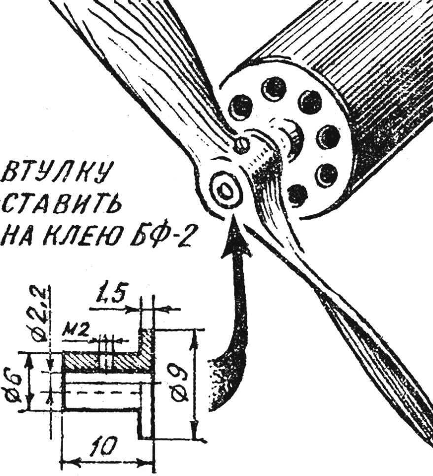
Fig. 4. Bushing mounting screw on the shaft of the motor (D16T).
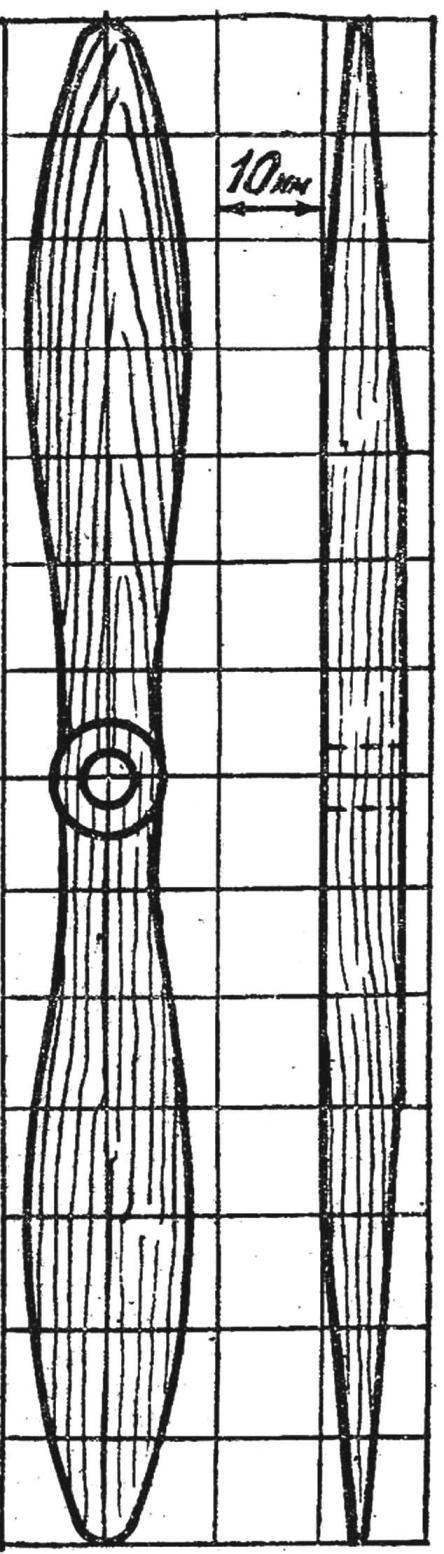
The propeller for the upgraded engine D-1-3.
This technology is also used in the alteration of the engines, der-40. The only difference is that the anchor of the engine EDR-40 is assembled from two anchors: axle rack up as many plates that the length of the anchor was equal to the length of the magnets. For this you have to either produce these records yourself, it is quite difficult to do, or to disassemble another engine.
The result of the adaptation capacity of the motor increases to an average of 1.5 times, and most importantly, dramatically increases the reliability of the brush mechanism. After final Assembly of the motor, fit the brushes to the collector and soldering lead conductors need to be attached to them 3336L battery through the ammeter and turn the back cover to find the point of least current. Then, changing the wires, find the same point in the rotation of the motor in the opposite direction. The position of the lid is fixed with two locking screws M2, which are screwed through the holes in the housing.
Upgraded motors provide ample opportunities for the creation of not only cord models with power through wires from batteries, batteries, or rectifiers, but lightweight models free flight type gliders with the quality of about 15-20. The optimum operating voltage in this case 6-7 V, power consumption — 2-3 A.
Greater increase in engine power is achieved by the spark, that is, placing in a single housing of a dual system of magnets and an elongated double anchors (with a corresponding change in the number of wires in the windings).
TIPS MANUAL. After rework and Assembly should drive the motor without screw on the stand at a voltage of 4.5 volts, including a few times for 5 min with breaks for 10-15 min. do This for running-in brushes to the collector.
Then you can put the screw and give a number of cycles of inclusions for 3-5 minutes, gradually increasing the voltage to 9 V. it should be pay attention to the sparking of the brushes and the degree of heating of the motor housing. If sparking strong motor will have to disassemble and check the status of a collector (it does not need to be grotty and clogged with coal dust) and fit carbon brushes to the surface. By the way, the purity of the collector must be checked before the flight. The surface of the plates is rubbed with a velvet cloth and cleaned with a clean cloth dampened with a light gasoline or acetone.
Bearings (bushings) shaft every 20-30 minutes of work should be lubricated with thick machine oil (preferably paraffin).
During transportation and storage models of electric motors must be protected from clogging, winding them with thin plastic tape.
S. PODGURSKY
Recommend to read
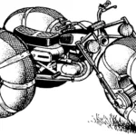 Pneumatic vehicle “Losharik”
Once upon a time, there was a popular TV show "You Can Do It" where craftsmen talked about the designs they had created. Perhaps it was there that information about air-cushion vehicles...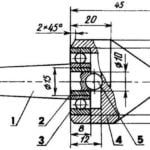 DURABLE CENTER
Woodworking lathes are designed to teach carpentry students in schools, universities and other educational institutions, and the machines home handymen often equipped with a tailstock...
