To ensure parallelism of the axes of the wheels and swing the levers need to assemble (weld) conductor. They are all equipped with silent-blocks from a motorcycle “Voskhod”, pressed from two sides via a spacer sleeve.
The frame is made using steel pipe Ø 33Х2 mm and Ø 16X2 mm. In the first place to weld the base frame, its middle bearing part. It is a quadrilateral with dimensions 920Х660 mm.
1 — steering column bracket (pipe Ø 33X2 mm, steel), 2. mounting bracket steering gear housing (steel, thickness 3 mm), 3 — mount plate front (steel, thickness 3 mm, 2 PCs.), 4 — mounting bracket of shock absorber (steel, thickness 2.5 mm, 2 pieces), 5 — strut mounting axis pedals (steel, pipe Ø 21X2,5 mm), 6, 7 — plate fixing mechanism of the wiper blade (steel, thickness 2.5 mm), 8 — windshield frame (steel, area 15X20 mm), 9 — plate mount rear view mirrors (steel, thickness 2 mm), 10 — rear frame (steel, pipe Ø 16X2 mm) 11 — cross member mounting rear shock absorbers (steel, Ø 30H3 mm), 12 — mounting bracket of shock absorber (steel, pipe Ø 34X2 mm, 2 PCs.), 13 — plate, fuel tank mounting and grid chipper (steel, thickness 3 mm, 3 PCs.) 14 — frame the installation of the battery (steel, area 15X20 mm), 15 — plate mounting side of the body (steel, thickness 3 mm, 2 PCs.), 16 — lever bracket pereklyucheniya gear (steel, thickness 2.5 mm), 17 — mounting brackets suspension arms (steel, thickness 2.5 mm, 8 PCs.), 18 — mounting bracket brake master cylinder (steel, thickness 3 mm), 19 — plate fuel tank mounting (steel, thickness 3 mm), 20 — arc top (steel, tube Ø 34X2 mm, 2 PCs.), 21 — plate docking hood and body side (steel, thickness 3 mm, 2 PCs.).
The view from the top, windshield frame, rear frame, and arcs connecting them, conventionally not shown.
Fig. 3. Assembly front control arm:
1 — bonded rubber Bush (2 PCs.), 2 — pipe Ø 32X2,5 mm 3 — spacer tube Ø 16X2 mm, 4 — axis (steel, Ø 12 mm), 5 — pipe Ø 28X 2.5 mm.
Fig. 4. Pivot bracket:
1 — clip (steel, thickness 8 mm), 2 — rod adjustment longitudinal tilt of the king pin (steel, Ø 22 mm), 3 plate (steel, thickness 2.5 mm), 4 — the emphasis of the head of the bolt. A — the installation location of the mounting brackets shock absorbers.
Fig. 5. Assembly-lever rear suspension:
1 — tube Ø 34Х2 mm, 2 — flange cradle support disc brake (steel, 5 mm thick), 3 — Bush (steel, pipe Ø 58Х3 mm), 4 — mounting bracket of shock absorber (steel, thickness 3 mm), 5 — stud M10, 6 — reinforcing plate (steel, thickness 2.5 mm), 7 steel rectangular tube 20X40 mm 8 — mounting plate brake hose (steel, thickness 2.5 mm), 9 — Bush bearing unit (D16, Ø 52 mm).
Fig. 6. Assembling the axle:
1 — the brake drum (motorized FDD), 2 — axis rear wheels (scooter VP-150M “Vyatka-Electron”.
Fig. 7. Assembly steering column:
1 — bushing (bronze, tube Ø 52 mm, 2 pieces), 2 — column pipe (D16, 52X3 mm Ø), 3 — the steering shaft (steel, pipe Ø 22 mm), 4 — flange of the steering wheel (steel, thickness 2.5 mm).
Fig. 8. Arm rear suspension with mounting brackets engine:
1 — front bracket (steel, thickness 3 mm), 2 — lower bracket (steel, thickness 2…3 mm), 3 plate racks engine (steel, thickness 2.5 mm), 4 — bracket tension roller (steel, thickness 2.5 mm).
Fig. 9. Wiring diagram:
1 — block the front lighting, 2 — flap control devices and switches, 3 — block ministarter, battery and relay control, 4 — block the back lighting, 5 — connecting bar and a fuse block, 6 — pin connectors, 7 — wiper unit and an audio signal; PL — lamp turn signal left, PP — lamp turn signal right, G — bulb position lamp f — lamp headlamps, NC — bulbs license plate light, With bulb-brake light, KLA — indicator lamp charge the battery, KS — a control lamp of a stoplight, KP — warning lamp for turn signal, KF — warning lamp headlight, RP — relay rotation ZZ — ignition switch G — key switch Parking light, f is the headlamp switch. the wiper switch, AC switch alarm, the navel of the switch of turn indicator, red — green-blue horn button, N, B, JS (R-R) terminals connect the relay-regulator, PR — connections to additional devices (fog lights, the seeker, etc.). — connections to the wiper, the C — terminals of the audio signal.
Fig. 10. Scan the front of the instrument cluster (D16, 1.5 mm thick).
The ends of cross pipes are not clipped and have to perform at 250 mm on each side. Then the base is installed on a level surface at an altitude of 230….250 mm. join (wire, clamps, etc.) front and rear suspension arms Assembly with wheels and brackets. Turning the mountings of the suspension arms relative to each other (around the pipe), achieve the desired position of the arms. The front wheels are installed with the collapse 1,5…2,5° rear vertically.
Final welding can be carried out only after making sure regularity and symmetry of the setting levers.
For anchoring the upper ends of the rear shock absorbers need to make brackets and weld them to the frame with two longitudinal pieces of pipe. Here welded frame for installation of the batteries and the relay-regulator, lugs for securing the fuel tank mounting body and a rear frame made of pipe Ø 16X2 mm.
The inverted U-shaped front cross-member serves to mount the lugs attaching the upper ends of the front shock absorbers. Below it is welded to the housing mounting steering and top — stops the shell drive mechanism of the clutch and the accelerator, mount the brake master cylinder, wiper mechanism, and finally the windshield frame. The latter is made from a steel angle section 15X10 mm; below it is welded in two parts to the installation of the wiper and the top of the plate for mounting the sun visors and rear view mirrors. The windshield frame and the rear frame are connected by two arcs made of pipe Ø mm. 34Х2 Windshield taken out of the sidecar; we did not like the height we added an element of Plexiglas with a thickness of 4 mm. to the surface and covered on both sides duralumin strip with a width of 10 mm, screw M3.
Front crossmember is also used for welding of plates and brackets body mounting.
To ensure the necessary rigidity of the frame in its design has two lateral longitudinal tubes connecting the front crossmember of the base frame (middle part) and the rear crossmember.
The steering column serves the purpose of directing and fixing the steering shaft and instrument panel and switches. It is made of aluminum pipe Ø 32 mm, slitted on both sides of the bronze bushings, which act as sliding bearings for the steering shaft.
As mentioned above, one of the objectives of little micro-car “RUTA” — teaching beginners to ride. Therefore, the set of necessary control pedals introduced an additional (fourth) pedal of the instructor. Shaft (rigidly connected) is tube Ø 16X2 mm with a length of 380…390 mm. the Rest of the pedals freely swinging on the axis. Therefore, with bolt M6 it is possible to block any pedal with the instructor (often in this role, the brake pedal).
But back to the frame construction. Stayed here to say that it is also necessary to fabricate and weld the mounting plate of seat belts and their locking mechanisms. We have used lap belts (these are used in tractors).
Electrical system performed according to the block diagram. The individual blocks are interconnected on the panel with 15 connection. Here you also may find the fuse box. Do not dwell on all the blocks, since they have standard layout. Consider only one panel of instruments and switches. This is the heart of the electrical system. Here you control and monitor the operation of all blocks.
The production starts with casing. The figure shows scan, which can be cut from a sheet of aluminum with a thickness of 1,5…2 mm. Explain the purpose of the holes. The upper part of the flap is a control system. The rectangular holes of size 20X30 mm are the “eyes” of the indicator lamps (from left to right, top to bottom): battery charging (red), brake light (red), direction indicators (green), middle (light yellow). Hole Ø 65 mm are used to accommodate the speedometer, in the block with the trip meter (motorcycle type).
At the bottom of the flap switches. In rectangular openings with a size 41X28 mm are rocker switches automotive: switches dimensions, low beam headlight, wiper mechanism and alarm.
In hole Ø 24 mm cuts into the ignition switch (used from TG-200 “Ant”); Ø 12 mm switch turn signals; Ø 14 mm — horn button (FDD); Ø 58 mm is used to exit the steering column. Four holes Ø 5,1 mm, need to fix the shield to the lugs of the clamp, located on the steering column.
Probably, the question may arise why “ROOT” is not equipped with headlights? We conceived (so Yes it really is) little micro-car for the city, according to the existing rules of the road to use high beam in city prohibited.
When the housing unit is made, bent and assembled, you can begin to cover. He is cut from viniplasta, celluloid, or any other polymeric sheet material. Bend it at the heated nichrome wire. Through hole Ø 20 mm displayed a flexible shaft drive cable.
The body of the micro-car, only “ROOT” is prefabricated and consists of a hood, sides and back. The place of junction of the hood with the sides runs vertically, along the axis of the front wheel. The joints of the sidewalls and the rear element parts are chosen at random based on the size and amount of available materials.
The hood is laminated integrally with the lower spoiler from fiberglass epoxy resin. For a mold should be cut out of foam a few panels: the top cover, two sidewalls, a front wall and a spoiler. After gluing the shape you need inside to reinforce the rib (also from foam). Then, the finished blockhead (pre-machined) fit required number of layers of resin-impregnated fiberglass in such a way that the overall thickness of the finished crust was the range of 1.5…2 mm. After this form is lowered in a well sealed plastic bag, having a slightly greater length than the dummy. The open side of the package is assembled and tightly wound to incoming inside the bag the rubber hose that joins the fitting of the vacuum pump. In the process of pumping air polyethylene, the form should constantly smooth. The pumping operation lasts 8 to 10 hours before the partial polymerization of the resin. This technology vyklicky, in our opinion, very advanced, labour-saving and allows to obtain a shaped product almost under the painting. Of course, the form can be made of other materials. The only condition is that the required strength.
As for the other panels and floor, all of them flat, or nearly flat. Made of fiberboard, covered both sides with fiberglass in one layer and are connected through different angles and plates with M4 screws (countersunk heads). To reduce the complexity of viskazivaniya hang them the better to Assembly and under load.
After Assembly of the body all joints, pre-cut at 45°, it is necessary to putty and viscoity. Then the body is painted in nitro enamel in 2-3 layers.
Chair also little micro-car is laminated glass, in the form of a trough. Inside seat and back cushions are stacked from automotive foam rubber, covered with imitation of leather or tapestry. Bolted the seat directly to the floor; adjust for length have not.
Brief specifications mini training car “RUE”:
Number of seats: 2
Base, mm: 1740
Track, mm: 1100
Ground clearance, mm: 170
Length, mm: 2560
Width, mm: 1250
Height, mm: 1400
Dry weight, kg: 270
Maximum speed with full load, km/h: 75
Engine: TG-200
Carburetor: K-62
Fuel delivery: diaphragm pump
Ignition system: magneto M 124 B1
Starting system engine: dynastream
Spark plug: And 17 In
Relay-regulator PP 121
Transmission: chain, type PR-12,7
Brake: hydraulic, drum on rear wheels
Fuel tank capacity, l: 12
KRYLOV, Vologda

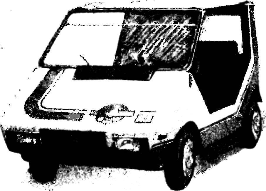 Our laboratory autocostruzione the House of young technicians stand on the court readers of the magazine “M-K” design of a micro-car, only. This time it’s “RUTA” — crew training car.