
 According to the rules of the competition model rocket must use only during takeoff the thrust of a jet engine, and the descent of the lifting force of the aerodynamic surface. For performance of requirements it is desirable that during takeoff the shape of the model was close to the missile, that is, would have a minimum lateral area. This requirement is most fully correspond to the model raketoplana with variable wing geometry. Very promising, in particular, the use of all-moving front wing, which at launch is located along the fuselage and therefore has little effect on flight, and the transition planning rotated across, providing the necessary redistribution of aerodynamic forces.
As experience has shown, most fully the advantages of the rotary wing are identified in models of aerodynamic configuration “duck”. The proposed model (see figure), despite the simplicity of the design, has good performance. At the Moscow regional competition of schoolchildren 1974 Alexander Fedotov with this model took first place, showing good result, despite the adverse weather conditions.
The model includes the rack-and-fuselage with engine compartment in the bow, a V-shaped arrow-shaped stabilizer, rudder, rotary wing, and mechanism of rotation and fixation of the wing.
The fuselage is made from pine slats for increased rigidity reinforced bottom, from the engine compartment to the stabilizer fin of the fake veneer. At the location of the rotary wing is further strengthened by side plates of lime, forming together with them the base plate for rotary wing. Engine compartment installed in the forward fuselage on the pylon, made of basswood. It consists of a tube, glued two layers of paper and pasted in her thin-walled cone of lime. To increase the strength of splices in the engine compartment with the pylon and the pylon with the body additionally pasted macalintal paper. Stabilizer, rudder and povs company commander the wing is made of balsa, but in its absence can be made of lightweight Linden correspondingly smaller thickness, so that the loss in weight will be negligible. The stabilizer and fin have a symmetrical profile and set at zero angles to the longitudinal axis. To increase the strength of the joints of the stabilizers with the keel and the hull strengthened zaletami. On the front edge of the stabilizers in 1/3 from the ends pasted anti-flatter weights streamlined shape, made of basswood.
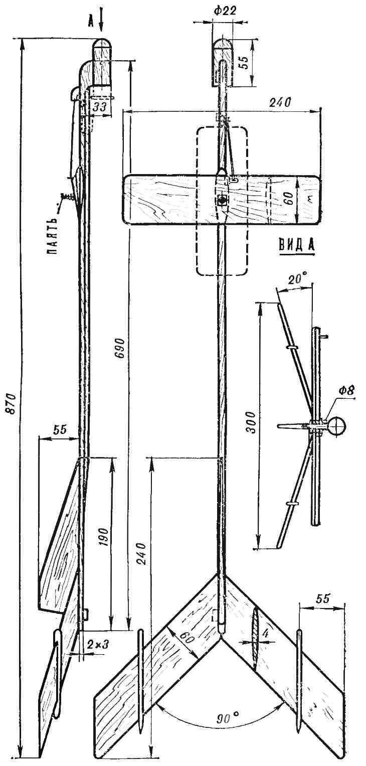
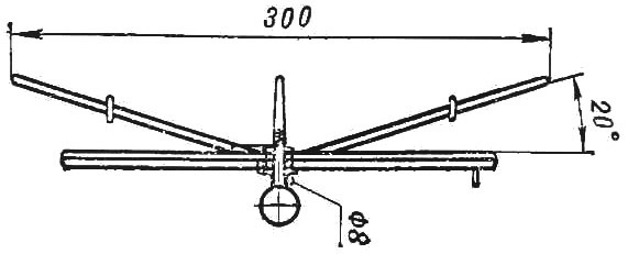
The wing has a PLANO-convex profile. In its centre is a hole with a diameter slightly larger than the diameter of the wire to the axis of rotation. In this place on the upper surface of the wing glued celluloid washer with a hole equal to the diameter of the axis of rotation and acting as a bearing. To the bottom is glued a thin piece of basswood wedge shape that defines the installation angle of the wing relative to the fuselage, the wing is rotated on an axis, made of wire and glued on the epoxy in the center of the base platform. Pressed the wing to support the site spring, the upper end of which is soldered to the axis of rotation. Fixing the wing in position along the body is provided with a wire cotter tied with a thin wire — Ø 0,3 mm to the motor housing. The check is inserted through the hole in the horn celluloid, glued to the left side of the wing, in a paper tube glued to the hull in the bow. When you go to the planning engine RCGO, firing, pulls the pin and releases the wing. Rotation of the wing in the transverse position is provided by tension of the rubber thread tied at one end to the wire “ear” glued to the front edge of the right wing, and the second to the same “eyelet” secured to the bow of the hull. Fixing the wing in position across the casing is provided with a rotation limiter, turning on when you turn the wing into the housing of the rod of the fuselage. The limiter is a segment of pine strips glued to the underside front edge of the right wing. In bow and aft parts of the hull are glued to the paper guide rings for takeoff. When planning for the model of the typical laminar flow regime. Therefore, the quality of surface finish increased demands.
After two coats of varnish the model can be covered or colored varnish, or a thin layer of paint. For the best Sliding of the wing on the supporting pad friction surfaces should be left unpainted and RUB them with a soft graphite.
Adjustment of the model is reduced to the selection of the installation angle of the wing relative to the body and eliminating the distortions of the wing and stabilizers, both own and relative to each other.
V. IVANOV, V. KUZMIN
Recommend to read
 “EDELWEISS” IN THE COUNTRY
Light truck, which I did for a holiday farm called "Edelweiss", is difficult to attribute definitely to any type of vehicles. He rigidly jointed (of two parts) frame. On the front of the... “Sawmill” in the yard
Mechanical saws produced by industry certainly make the work associated with preparing firewood for the winter easier. But most of them have one drawback: during operation, the entire unit...
