THREE BLADES ARE MORE RELIABLE

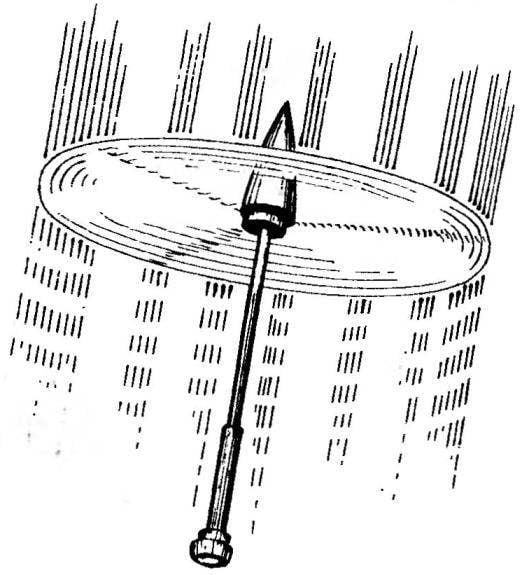
We continue to publish models of rotochutes — winning flying competition for the Cup named after S. P. Korolev. Model Cup holder yurtaeva S. (Moscow) are described in the “Modelis-the-designer”, No. 4, 1999 Today we offer developed by the Tsentr detskogo tvorchestva g. Nizhnekamsk, under the leadership of teacher A. N. Rossiia rotocut, which was the prize-winner of these competitions V. Stolyarov. Model rotocut class Ѕ9А — lobed. The fuselage is in two parts: the rod and propulsion of the container; the connection — telescopic.


Work on the model begins with the manufacture of the fuselage. First, on the mandrel with a diameter of 10.2 mm roll container made of two layers of fiberglass with a thickness of 0.1 mm and cut along the length 125 mm. In the lower part of the fixed tail fairing lime. It has three longitudinal grooves with width 4 and depth 3 mm for placement of clamps blades. Then on the outside of the fairing around the circumference-~ mathiaut four layers of thread, which, in turn, will keep the blades from disclosure.
 
In the upper end of the container is glued face frame with a hole diameter of 6 mm. In the wall of the container, drill drainage holes (5-6 pieces) for gas exhaust when triggered, expelling charge.
 
Rod length of 300 mm, and the container vyklevyvajut of glass on the mandrel diameter of 5 to 5.5 mm. you Can make it from wood, but then its strength will be lower.
At a distance of 85 mm from the top of the rod is mounted the node of attachment of the blades. It consists of a power frame and snap ring. The frame is cut from foil fiberglass with a thickness of 1-1,5 mm, make it three curly cut (angle 120°) to accommodate the levers of mounting the blades.
 
To the bottom surface of the frame is glued solid ring width of 7.5— 8mm, which will serve as a focus for leverage disclosure of the blades. To produce this ring of ten layers of fiberglass or carve aluminum. Power frame glue on the rod with epoxy.
 
Three-blade rotocut:
 
Three-blade rotocut:
 
1 — fairing head; 2 frames; 3 — rod; 4 — blade rotor; 5 — stabilizer; 6 — a tail fairing; 7 – lock of the blade, starting; 8 — drain hole; 9 — container of the engine; 10 — hook the rubber rod; 11 — thrust of the disclosure of the blade (rubber); 12 — thrust; 13 — axis of rotation of the blades; 14 — control arm of the blade; 15 — frame power; 16 — frame segment.

 
The hinge levers of the blades cut out from glass fiber plastic with thickness of 1.5 mm. On folded side, make two holes at a distance of 6.5 mm between 1 mm underneath the axis of the lever and a diameter of 2 mm for the rubber traction. Steel wire 1 mm diameter hollow out U-shaped the axis of rotation of the blade, threaded through a thin hole of the lever and soldered it to the top surface of the power frame. In another hole (2 mm diameter) secured with a rubber thread to the disclosure of the blade. The second end of the thread wear on a hook, fixed on the rod.
In the bow of the rod to glue one or two the frame and attach the fairing that is molded from fiberglass. The lower (free) end of the rod threaded through the top opening of the container and secured therein the piston is carved from basswood. It is a kind of telescopic connection.
 
The blades (three of them) are made from balsa plates which thickness of 1.5 and a length of 250 mm is moistened, laid on the mandrel with a diameter of 30 mm and wrapped with a bandage or rubber strap to give the required shape. After drying, each blade covered with two layers of nitrocellulose lacquer. Then on one end make a longitudinal cut with a width of 1,5 and length of 37 mm at the lever hinge, and to the other attach the stabilizer is also made from balsa. In the same place, on the lower plane of the blade is glued a plate made of fiberglass with a width of 3.5 and length of 30 mm—clamping starting position of the blade.
 
In the ready cutouts of the blades glued the notched levers of the linkage. The angle of deflection of the blade handle, needle files podpilivaya the notches in the thrust ring.
 
The model preparation of Rotorua is carried out in such sequence. Fold the blades along the rods, and thus move up the motor container. His tail fairing is included in the ring formed of three arcuate blades, the clamps which, in turn, is inserted into the longitudinal grooves of the cowling. Externally, it turns an ordinary model rocket. Remains to install the engine (MRD). The mass of the model without it-26 g.
 
Model rotocut takes off from a gasdynamic installation. After liftoff, at an altitude of 200-250 m, work when you shibei charge, the piston rod goes up (for no more than 10-15 mm), the blades are released from fixation and under the action of the rubber rods revealed — the model goes into autorotation.
 
V. ROZHKOV

Recommend to read

  • SCREW – ON COPIERSCREW – ON COPIER
    Fixture is used for manufacturing propellers boat on lathes Тb-4 and TV-7. Using the tool it is possible to produce propellers of aluminum alloy (D16T), brass and plastics. Moreover,...
  • ALMOST LIKE A CANALMOST LIKE A CAN
    During the canning of vegetables and fruits have to deal with wet and hot banks that need to move or carry. So they don't burn or slip out of hands, lignite from a piece of wire with a...