Fig. 2. Mount the blades to the rotor hub:
1 — rotor hub 2 — pin, 3 4, 5 — pins, 6 — lock washer, 7 — rod, 8 — axis of the blade, 9 — bushing hinge blade, 10 — restrictor mounting angle of the blade, 11 — blade.
Fig. 3. Bearing:
1 — housing (D16T), 2 — Bush (St.).
The Assembly of the attachment of the blade and the hub 3 of the rotor is produced as follows. Rod 7 (see Fig. 2) put in the grommet 1 of the rotor. The holes in them combined. In hole Ø 3 mm insert the 2 pins that are secured with locking pins Ø 0,8 mm on both sides. These cotter pins upon impact of the blade on the ground are cut off, thereby maintaining propeller. On the axle 8 fits over the sleeve 9, which is held in place by washers and pins so that axial clearance ensures that the blades 11 are free to rotate.
Sleeve 9 is inserted into the bar 7 and tightening the collet Chuck of the limiter 10, which is pre-put on the rod. Then use M2 screw in the legs of the limiter sets the angle of attack of the blades in the range of +22 and -7°. It is the position of the limiter finally fixed. Assembled bushing mounted on the shaft of the model a collet Chuck.
Currently, helicopters are requirements as to semi-copy with a specific midsection, so the fuselage is made with an oversized cabin, which together with the lantern of shaped fiberglass. The toe of the fuselage has a bend from plywood with a thickness of 1 mm. Tail boom made of balsa wood with a pine trim at the top and bottom. On the end installed a keel in the form of a ring Ø 120 mm, covered with transparent film.
The nose and tail boom attached to the tube of the housing 1 (see Fig. 1) six M3 screws.
To reduce the flight weight of the model in a tube shell with both ends glued on the resin sliding bearings 9, through which passes the shaft 2 of the rotor of the dural tube (outer Ø 9.9 mm, wall thickness 1 mm). At her with one hand wearing sleeve 3 of the rotor, and with another — tank-engine mount 10.
Of great interest to modelers is the tank-engine mount. Were developed two variants of its design. Earlier — version 1, last — option 2. Both designs are made on a lathe from duralumin D16T, and the individual elements (flange, groove for the needle and nozzle, collet) fine-tuned manually.
These designs allowed us to abandon the separate manufacture of the motor and tank to reduce the weight of the helicopter. In addition, this tank-engine mount enables quick Assembly and disassembly of the model.
As can be seen from the figure, the tank-engine mount “Option-1” is attached to the shaft by a screw passing through. This scheme was not the best, since the through hole in the shaft is centered the tension and the shock shaft broke at the drilling point.
The design of the tank “Option-2” has a clip-type collets, which further reduces the time of Assembly and disassembly of the model.
Air being sucked into the engine through the hollow shaft of the rotor, the end of which is inside the tank rests on the diffuser.
In the manufacture and installation of tank-motor, great attention should be paid to its alignment relative to the motor shaft, since any slippage creates significant run-out and impairs the flight of the apparatus.
In the tank “Option-1” cover secured by six screws M2 through a pad, and a “Version-2” naniniwala glass, carving its pre-smeared with epoxy.
Fittings for tanks machined from steel and glued into epoxy resin. Filling and drainage are installed as close as possible to the rotor shaft, from the top of the tank, feeding as close as possible to the outer side of its surface, on the bottom. This location fittings provides uninterrupted supply of fuel and eliminates it from leaking during the rotation of tank-motor. The latter is attached to a rectangular flange 28X28 mm to the rear of the crankcase. Is the markup holes for the nozzle and needle, which are drilled and finalize a needle file to the required shape.
V. DVORKIN, Kharkov
Recommend to read THE “SECRET” ENTRANCE HALL Behind the scenes of the hanger, if you make it movable, might be available in your hallway, a closet or even a pantry. Such "double" the solution to a home wardrobe combined... OPEL ASTRA CABRIO Premiere of the OPEL ASTRA CABRIO was held at the Geneva motor show in 2001. It is worth noting that the firm already supplies Opel to market hatchbacks, sedans and coupes of the family... 
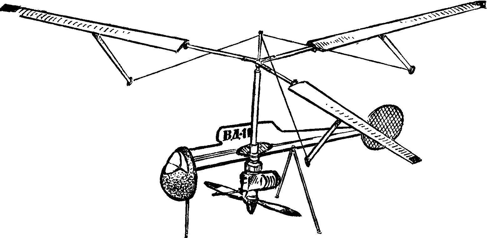 In aeromodelling clubs of the pioneer of the Kominternovsky area, obsut and Kharkiv high school № 112 in a few years, work is underway on the co-axial model helicopters. Their designs are different, but they steadily fly. The following model is one of the latest versions. In the competition “Experiment 78” in the class of timed models of helicopters, she won first place.