
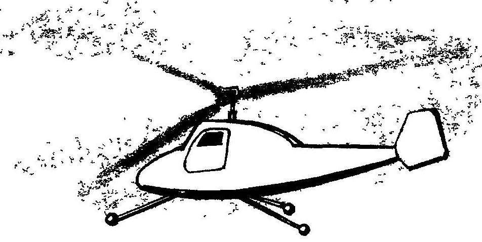
 Svobodnaya model helicopter. As they say, is new — is well forgotten old. Not so long ago we introduced readers model airplanes from the simplest Svobodnaya model helicopter — judging by the responses, a mini helicopter like you, our readers, Some even took the model for something contraption, missing in the article is the observation that these helicopters modelers created and launched in the early 50-ies of the last century.
Our magazine has for many years supported this kind of modeling — Svobodnaya mini-helicopters that were included in the experimental models, participated in the annual competition “Experiment” for the prize of “Modeller-designer”, which regularly published drawings of the most interesting designs
In this issue we introduce the readers with another Svobodnaya model helicopter. Its characteristic feature is the asymmetrical rotor, which is driven in rotation mounted on the rod compression engine with a propeller.
Rotor models — a two-bladed, steel — blades are arranged at an angle of 120 degrees relative to the rod fixed thereto by the engine In the center hub of the rotor blades is fixed not rigidly, with axial and horizontal hinges, allowing them to samoustraniajutsia in flight with optimum angle of attack. Balancing each of the blades is carried out using a stabilizer and load, fixed on the beams of duralumin spokes with a diameter of 3 mm. In essence, each of the blades according to the scheme does not differ from cord model aircraft flying on the hard cords around a Central hub of the Blade — mixed design. Each of them is made from foam stamps PS (suitable construction, and packaging) and is reinforced of pine rail-the spar and leading and trailing edges and wingtips.
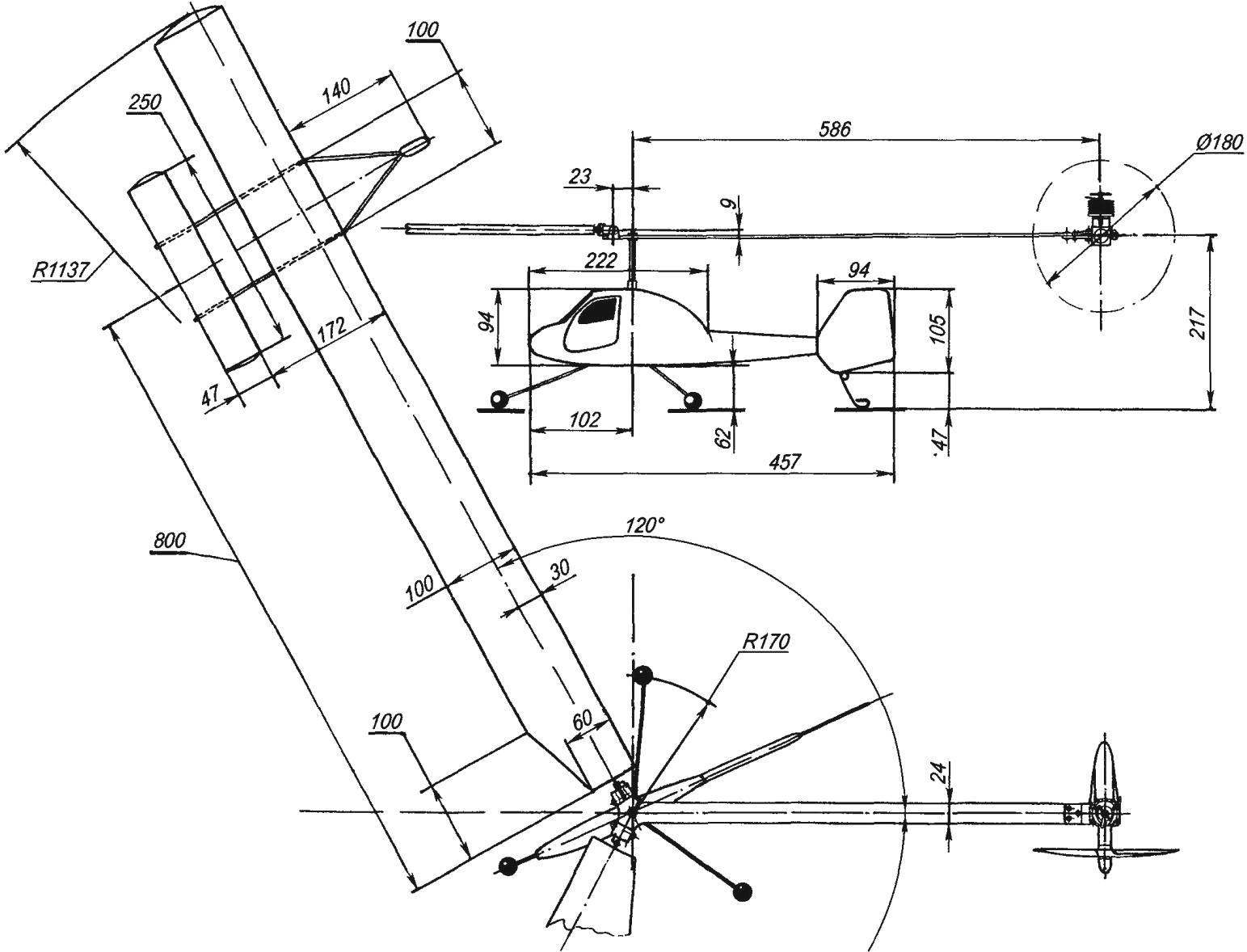
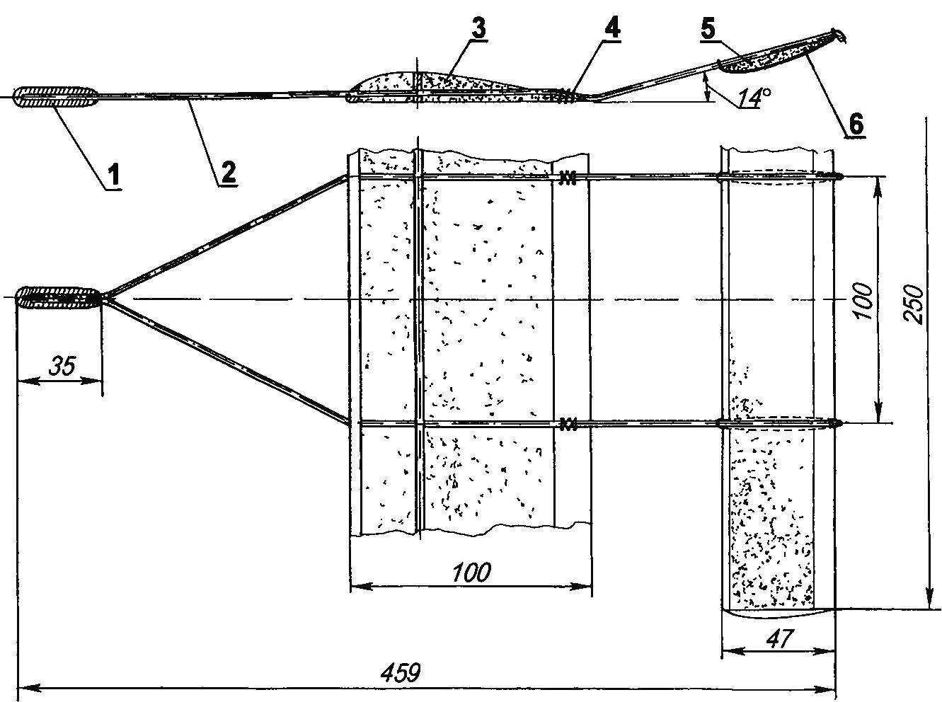
Geometry Svobodnaya model helicopter (for the planned projection of the fuselage is conventionally rotated)
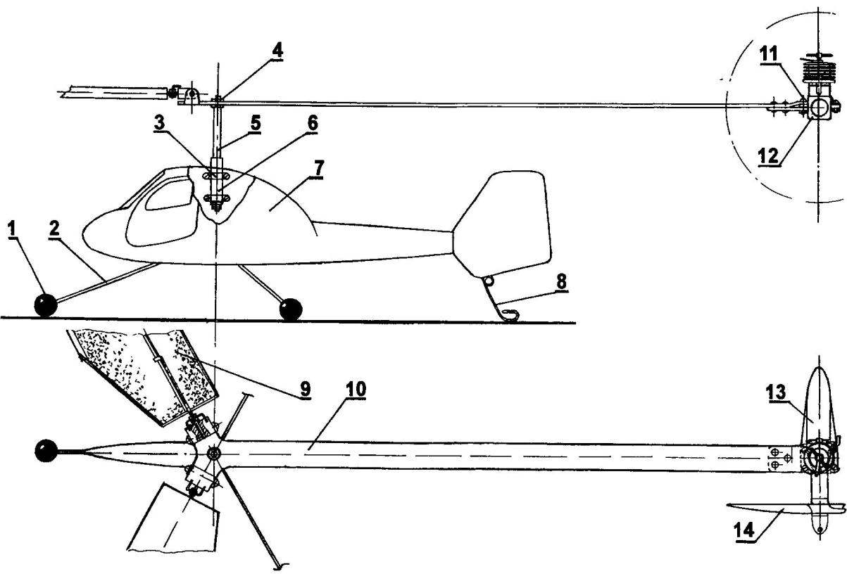
The layout of the model helicopter:
1 prop (plastic ball Ø20), 2 — spring chassis (steel, wire EOD Ø3), 3 — collar (aluminum, strip 1×10), 4 — nut M5 mounting sleeve of the rotor, 5 — rotor shaft (steel wire Ø5), 6 – bearing, 7 — body, 8 — crutch (OVS wire Ø1,5), 9 — blade; 10 — rod (made of anodized aluminum, sheet s3) 11 bolts M3 motor mounts, 12 — engine MK-17 “Junior”, 13 fuel tank 14 air screw Ø180
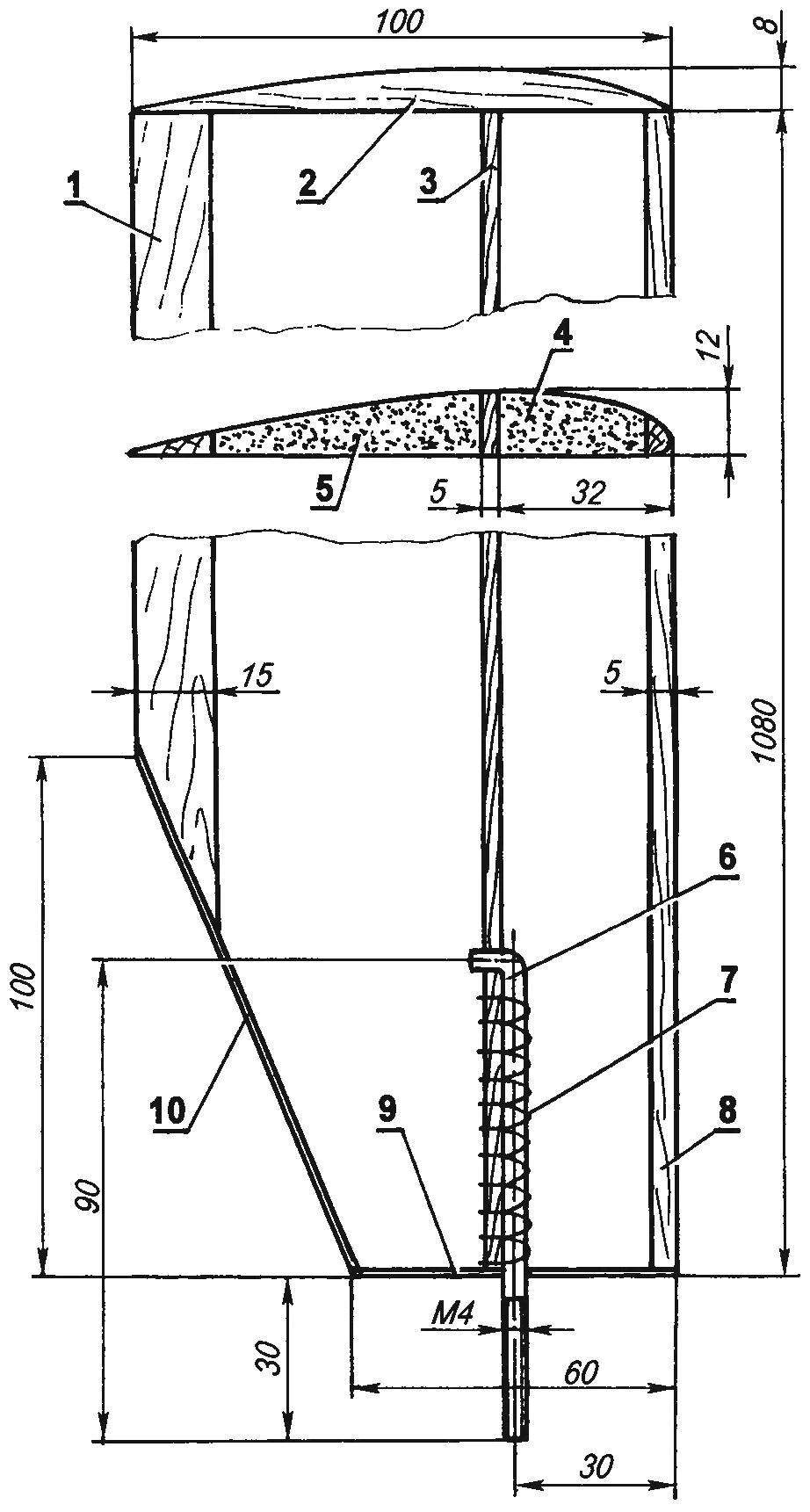
Carrier blade model helicopter:
1 — trailing edge (pine, rail 4×15); 2 — ending (Linden), 3 — longeron (pine, 5×13 rail), 4,5 — foam filled, 6 — longitudinal axis of the blade (steel, wire Ø4); 7 thread mounting axis to the side member 8 is the front edge (pine, rail 5×8); 9,10 — banding (Linden, strip s2)
The first step is to cut telephonophobia blanks blades — this is best done with nichrome wire-strings, heated by electric current While the surface will be vitrified crust, which will allow to abandon their subsequent pasting paper or Mylar film. Nichrome string must be installed in a wooden frame — the same as luchkovoj saws-hacksaw Power to thermoresin should be served from a network through Latr in order to be able to choose the best heating temperature.
For cutting you will also need a couple of templates made of aluminum in accordance with the cross section of the blade — they are fixed to the ends of the foam blank and serve as guides in processing the foam.
Cut the foam blades are cut front and rear edge and epoxy glued pine slats. Further, from the body parts of idol lines spaced at 30 mm from the leading edge, cut a strip of 5 mm thick and it is glued to the spar from pine slats with a cross-section Pre-13×5 mm. with thread and epoxy glue is fixed to the longitudinal axis of the blade, bent in the form of the letter “G” made of steel wire with a diameter of 4 mm. On the outer end of the shaft threaded M4. The finished blade is polished and covered with a thin layer of epoxy resin.
The rotor bushing is made Zatsepa the post engine sheet duralumin of a thickness of 3 mm. the Engine is attached to the shaft of the console — two bolts and M3 nuts for the right support. Fixing unit represents a sort of plug formed by a rod and riveted to her plate. Note that the bar might make sense to take longer than indicated in the drawing, by approximately 100 mm and the final length to choose when balancing of the rotor — this will allow to do without additional loads on the blades
As mentioned above, the blades installed in the rotor hub hinge. Each of the horizontal hinges formed by a pair of bent ears with holes 4 mm in diameter, which are fastened with screws dural biscuit with a threaded hole in the longitudinal axis of the blade. The movement of the blade in joints is limited by the limb on the rotor hub preventing the overhang of the blade, and an emphasis on longitudinal axis, providing maximum angles of attack from -3 to +15 degrees.
The foam stabilizer is also edged with pine slats, its maximum thickness is 5 mm. As already mentioned, wing stabilizer connects using two aluminum knitting needles with a diameter of 3 mm — bending them, you can change the installation angle of the stabilizer, which in turn allows you to adjust the angle of attack of the rotor blades. The optimum angle of attack of about 10 degrees. Front spokes are connected with the lead cargo mass is determined experimentally, in the same way as when balancing a model glider or plane blade about its longitudinal axis, is located on the line 30 percent of the chord must be in a state of indifferent equilibrium.
Stabilizer:
1 — the load (lead), 2 — a knitting needle (aluminum, Ø3), 3 — blade, 4 — nylon thread attachment of spokes; 5 — stabilizer, 6 — rubber ring for stabilizer
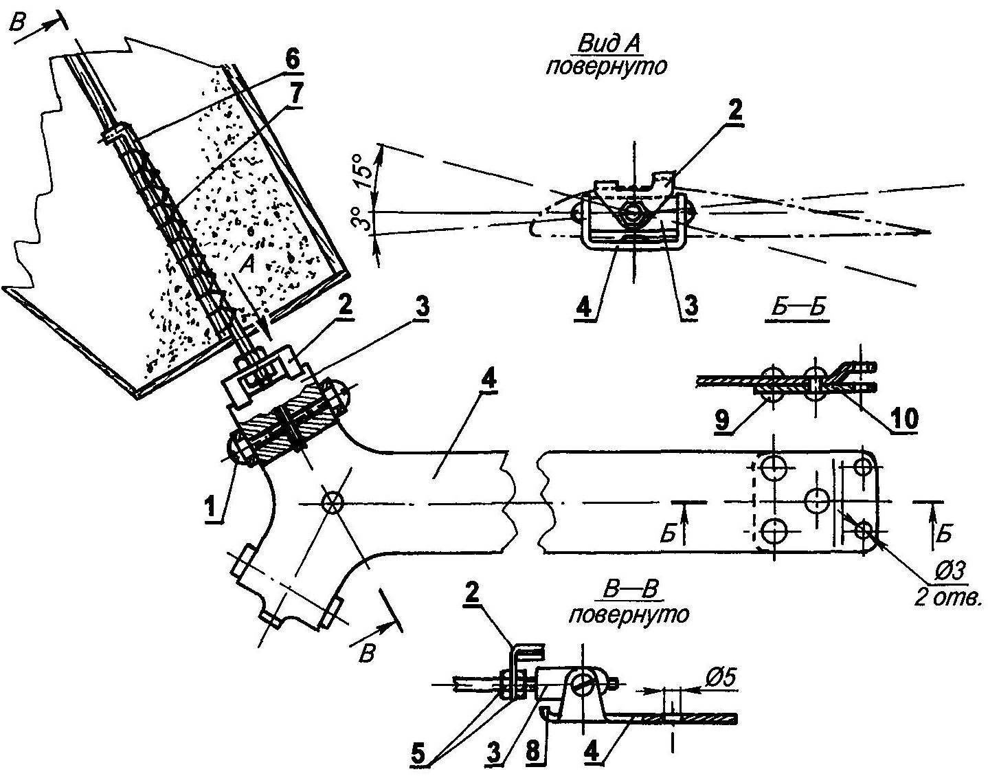
The Central hub:
1 — axis horizontal hinge of the blade (M4 screw, 2 PCs.), 2 — stops angle of attack of the blade (made of anodized aluminum, sheet s2), 3 — Sukhar hinge (aluminum); 4 — rod —based Central hub (aluminum, sheet s3); 5 — M4 nuts mounting the end stop; 6 — longitudinal axis of the blade; 7 thread mounting axis of the blade, 8 — limiter of overhang of the blade (the limb to the Central hub); 9 — rivet Ø3. 10 — panel (aluminum, sheet s2)
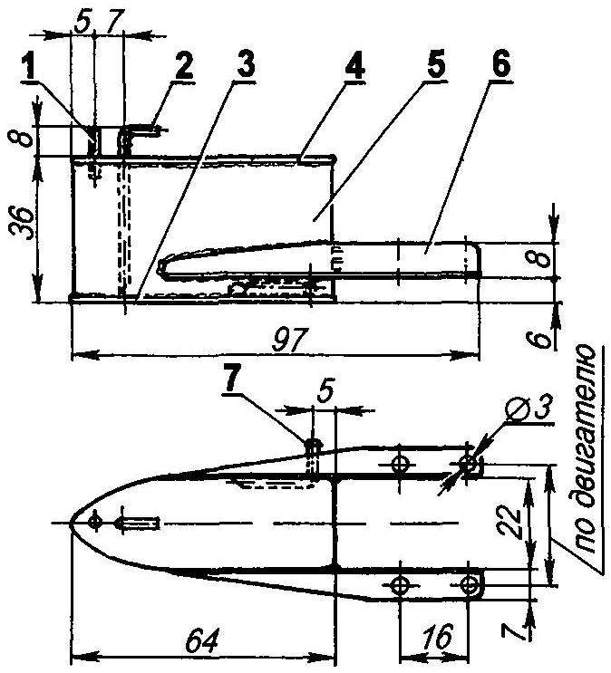
Fuel tank models:
1 filling tube (copper tube 4×0,5); 2 — drain pipe (copper, tube 4×0,5); 3,4 — base tank (tinplate s0,3); 5 — shell (tinplate, s0,3), 6 mounting brackets (galvanized steel, sheet s0,8); 7 — tube of the engine (copper, tube 4×0,5)
The fuel tank is streamlined with a capacity of about 40 ml is located directly behind the engine and attached with M3 screws to the Tank it supports soldered tin plate 0.3 mm thick — it consists of two identical bases and sides. Tank embedded in three copper tube — feed motor, gas and drainage; the first is connected with the inlet of the carburetor polyurethane kembrikom. Mounting brackets represent the angles bent from galvanized roofing iron with a thickness of 0.8 mm and soldered to the tank.
The base of the fuselage is a plywood plate with thickness of 4 mm, on which are mounted the bearing Assembly of the rotor and the chassis. The bearing Assembly consists of a segment of dural tube in which are fixed two plastic bushings — bearings. On the fuselage this node is fixed with the help of a pair of aluminum clamps, bolts with thread M3 and nuts.
Spring chassis made of steel wire with a diameter of 3 mm, at the end of each spring fixed bearing — plastic balls with a diameter of about 20 mm.
After Assembly to the base of the fuselage glued the foam sidewall. Thus prepared vyshkurivaetsya fuselage, primed with epoxy glue, align the two-component automotive putty, again vyshkurivaetsya and painted with enamel.
It should be mentioned that before starting it makes sense to fill the Central tank portion of the fuel at a certain time of flight from three to five minutes. When you stop the engine the model is quite stable authorative, with swiveling blades automatically reduce your angle of attack.
I. SILVER
Recommend to read
 DEFENDER RADIO
The proposed device is designed for "soft" on various radio and electrical household AC voltage of 220 V it is Known that the moment of switching devices containing a primary or...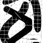 THE RETURN OF THE BOOMERANG
40 SECONDS IN THE AIR, THE RANGE OF DIRECT FLIGHT 114 M AND THE TOTAL LENGTH OF THE TRAJECTORY IS ABOUT ONE - THIRD OF THE KILOMETER- THESE ARE RECORD FIGURES RECORDED BY THE...
