WITH ELEKTROLETA ON A WALK

ELEKTROLETA FOR A WALK

Speed, racing, training, training, flight, control line, radio control room – which only the definitions used to describe the purpose and characteristics of a particular flying models, not come up with designers and pilots! And when I decided to design another microplane, first of all think about what definition to give to this new aircraft. It is known as an aircraft name, so it will fly.

RC model airplane motor


First of all, I set a goal to use to create models of accessible materials, based on the weightless and at the same time are quite affordable foam technology which has long been worked by the modelers. Then I thought about the purpose of the aircraft, defining the term “walking”, that is, possible, quite slow and easily managed. And finally, as the power plant chose the motor that’s in contrast to the internal combustion engine does not cause the Modeler to unnecessary trouble in the operation of the model. The result was that “a pleasure craft foam RC model airplane motor”.
 
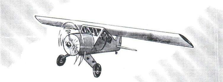
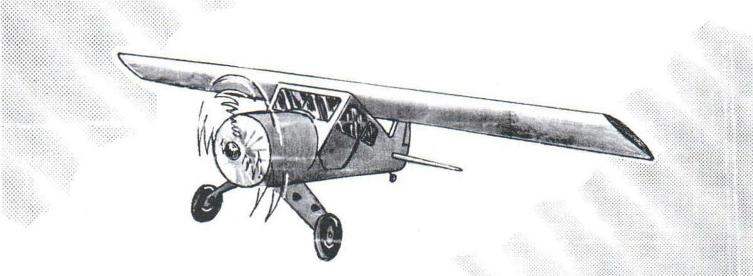
RC model airplane, which I propose to make to our readers is a high-wing monoplane, characterized by ease of piloting, good stability and excellent landing characteristics.
 
As mentioned above – the main structural material in the manufacture of the model is foam – or rather, foam ceiling panel thickness 3 and 6 mm, which was fabricated most of the parts of the model – including frames and planking of the fuselage, horizontal tail and wing and the elevators and ailerons.
Of course, the foam material although a lightweight, but his strength and the modulus of elasticity is insufficient for the manufacture of a number of elements flying models -for example, fuselage frames, wing skin and ribs. However, these details can enhance the paste over, for example, foam frames and ribs drawing paper using glue “Titan” (it is designed for mounting to walls and ceilings, foam panels, rosettes and ceiling moldings). Lately, modelers began to use to strengthen the foam wing panels heavy-duty manorastroman thread -the wiring of them, in particular, contains the cords with vinyl-coated sold in hardware stores as clotheslines. In order to enhance, for example, wing, a pair of such yarns diagonally privor-movemeut using the same “Titanium” on the outside of the wing panels, which increases the strength and rigidity of the wing as in bending and in torsion.
 
Fig. 1. The geometric schema of
Fig. 1. The geometric schema of “walking” elektroleta
 
Fig. 2. Design elektroleta
Fig. 2. Design elektroleta:
 
1 – propeller; 2 – fairing (plastic); 3 – pipe of the engine nacelle (Vileika of epoxy resin and drawing paper); 4 – frame No. 1 (s6 foam, covered with drawing paper on an epoxy binder); 5 – frame № 2; 6 – servo control Aileron; 7 – frame № 3; 8 – receiver of remote control equipment; 9 – servo control rudder; 10 – frame № 5; 11 – control rod rudder (aluminum knitting needle d3); 12 – control rod elevators (dural knitting needle with a diameter of 3 mm); 13 – Kiel (foam s6); 14 – rudder (foam s6); 15 — elevators (foam s6); 16 — stabilizer (foam, s6); 17 – the tail landing gear; 18 – the shell of the fuselage (foam s6); 19 – steering machine of the Elevator control; 20 – battery (12 batteries); 21 – motor type SPEED 900; 22 – wheel chassis d50 (children’s toys); 23 – self-tapping screws mounting spring suspension; 24 – spring chassis (aluminum s3); 25 – the wheel axle of the chassis (M4 bolt with two nuts); a 26 – stringer (pine, battens 3×3); 27 — support wing (pine, rail 3×80); 28 – of the reference area of the wing (Linden, s3); 29 – the plug (lime), 30 – frame № 4; 31 – frame № 6
 

Manufacturer model it is best to start with the fuselage. The first thing to depict his theoretical drawings in scale of 1:1, and then according to it a wooden block section 90×120 mm cut disc understated its outline of the theoretical drawing of 6 mm thickness covering the future of the fuselage.
 
Shaping the future of the fuselage is made on a wooden bar warmed by a powerful Hairdryer 6-mm Styrofoam panel. At the same time the softened preform primitives to the disc of elastic medical bandage. The degree of heating of the foam is pre-determined on scraps of foam slabs of appropriate thickness.
 
Further in accordance with the theoretical and technical drawings of the 6-mm Styrofoam panel reinforced on both sides of the drawing paper, cut out the frames and use glue “Titan” are pasted on the designated space.
At the front of the fuselage frames No. 1 and No. 2 set forth his whose diameter corresponds to the diameter of the used electric motor (in particular, SPEED 900 – 35 mm). In the rear of the tube pasted a fake cover, where a couple of screws-self-tapping screws fixed spring chassis.
 
The pipe wikiepedia on a cylindrical rod made of a few turns of drawing paper and epoxy resin. After curing of the connecting rod can be removed from the pipe, it is made from two obliquely arranged parts connected by a pair of screws-screws, and wrap two layers of ultra-thin (the so-called “food”) film.
 
Fig. 4. Horizontal tail
Fig. 4. Horizontal tail:
 
1 – stabilizer (foam s6); 2 – Elevator (foam s6); 3 – hinge hinge the rudders

 
Figure 5. Manufacturer hinges hinge the rudders and ailerons
Figure 5. Manufacturer hinges hinge the rudders and ailerons:
 
1 – skeletons of half-loops (Linden, s0,5); 2 – nylon or Mylar thread; 3 – needle

 
In the front part of the fuselage, the tube is fixed also carved from foam cone.
 
Wing elektroleta also the foam consists of the following main parts: top and bottom panels (3mm foam), two spars (6-mm polystyrene foam), the twelve split ribs (6 mm foam) and front and rear edges. The upper and lower wing panels should be reinforced with heavy-duty filaments diagonally preformula them to the outside surfaces of the panels, spars – a couple of threads on their upper and lower sides, and cut the foam ribs pasting them on both sides of the drawing paper.
 
The curves of the front parts of the wing panels in accordance with his profile, you can perform by pushing the foam workpiece to the heated over the flame of a gas burner steel pipe of suitable diameter. Before proceeding to experimentally determine the degree of heating of the pipe, cranking it trim the foam.
Wing Assembly is made on the bottom panel – at first it are fixed by glue “Titan” spars, front and back edges, then cut into three pieces of ribs.
 
The ailerons of the wing foam also driven by a torsion bar, made of aluminum knitting needles with a thickness of 3-4 mm. Hinge each Aileron is made using three loops, made of plates of 0.5-mm lime veneer and nylon yarn, are wound in a “figure eights” around the next pair of fixed plates. Fixing the hinges in the ailerons and the wing is made using a glue “Titan”.
 
Kiel, horizontal tail and rudders and height made of 6-mm plates of foam. The installation of the rudders is exactly the same as the linkage of the ailerons.
 
In the process of making elektroleta should periodically check its alignment – our model center of gravity should be located at a distance of 25 – 30 percent of the wing chord, measured from its leading edge. If the position of the center of gravity is outside these values, sometimes have to rearrange the model to move forward or backward the motor, battery pack, receiver, remote control equipment. In a pinch, you can shift forward or back the wing itself.
 
For finishing the foam parts makes sense to produce a homemade set of files from plywood strips and glued them sandpapers of different grits. Paint electrolet enamels nitroosnove not necessary, since the polystyrene dissolves them very well. Better to use acrylic (latex) paint.
 
The first flight is best done by hanging electrolet on durable filament fixed in the center of gravity of the machine and turning his nose to the wind. On this simulator you can learn to enter the airplane in roll and withdraw from it, to carry out the dive and pitch up. Getting to the flights, be aware that the platform for take-off, most likely, is not found. To send the model in flight will have with the help of an assistant, who will do it energetic cast. However, you can do without an assistant, if you use a simple catapult, which is a smooth shield with dimensions 0,5×3,0 m, which is assembled from strips of 3 mm plywood. In the front part of the shield is secured a rubber cord is stretched and tied with string “on the bow” at the back of the shield, after which he set on the earth with an inclination of 10 – 15 degrees. At startup, the motor is activated the model, then the pilot pulls the string, the bow untied and rubber cord, geared to the wheels of the chassis, sends the model in flight.
 
If the area of the flights have smooth dirt or asphalt runway with a length of about 50 meters, then you can try to master the classic fit, but for beginners it is best to recommend landing on a meadow with high grass. In this case, the model is aged at a height of about 50 centimeters above the grass to stall speed, after which the elevators are transferred to the pitch and should presyterian, which will save your model.
IGOR MNEVNIKI

Recommend to read

  • CAN BE ALONECAN BE ALONE
    Two-handed saw because so called that it requires the application of tractive effort of the two hands for which at each end there is inserted on top of the wooden handle. But experience...
  • “BOOM” — CENTER“BOOM” — CENTER
    For a couple of minutes of paper or paperboard will be able to make strenuously device that will instantly show you the centre of any circle, for example, the base of the cylinder. The...