The simplicity of the resulting construction, of course, affect the high reliability of the MB “Pony”: for more than three years of hard use — not a single significant failure. Well, if failures happen, the fault of the starting device of the engine, where, as it turned out, set the fragile spring (so it makes sense to take care of a spare or even get a “usacom” made by another plant).
But back to the consideration of structural features of the main gearbox. Frame with its drive shaft connects the two bearing 206. Moreover, the ends of the shaft, entering the drive axles of the wheels, be with them due to the bolt connections single unit. At the ends of the axle shafts are taken from the agricultural machinery one-way clutch, which are attached to the wheels.
With a choice of wheels had a lot of trouble, because when the small mass of Pony they need to create optimal grip with the ground. Tried all sorts (from solid metal to pneumatic-tired machines with different types of lug), and did not stop until invented by the same design team — set to rim from the car “Zaporozhets” soft radial tires with universal tread (from “the Zhiguli” or “Moskvich-412”), and not filled with compressed air, and… rubber. More precisely, the four lateral half-rings, cut to the tread of the two old “diagonale”.
In my own experience I know how difficult it is to squeeze such elastic workpiece inside a working bus, “zabarte for a purpose” on the disk. Without heavy hammer, “crowbar” and blunt chisel is not enough.
On each wheel walking tractor krupeshina chain mounted with diagonal intersections. It performs double duty: keeps the tire from turning and serves grantsa-flail. With wheels, reminiscent of the leggings tied with bast, “Pony” has never stalled. However, maneuvers on the asphalt, it performs with much less ease than, say, in the field. Therefore, when you use MB as a vehicle on good roads (especially when surrounded by nothing but asphalt or concrete) wheel”boot” changed to pneumatic-tired machines.
Steering the “Pony” motor type. On the left side of the steering wheel located lever “gas”. Used lever of a fuel corrector of the carburettor from the “Tula” that allows you to record “gas”. There is also a toggle switch “ignition” (it also serves to stop the engine). Below is the lever of the clutch. All: no more, no levers, no pedals.
For the driver fitted the soft seat of the scooter “Tula”. Located on a connecting node, it allows you to choose a comfortable fit for different types of work.
The very same docking station, performing many additional functions, is a rod with a welded strip of iron with a thickness of 8 mm. On the last fixture for the seat and the flange of the propeller shaft with the internal splines. Pull through the turning device is fixed to the frame and has the ability to turn left and right, and around its axis. The first allows the driver to control MB, and the second greatly facilitates the execution of turns when using the “Pony” truck. Here is the site angle adjustment of the towed guns, which is very important, in particular, to adjust the vertical position of the plow.
In addition, the connecting node are also footrests for the driver, the fastener of the plough and the lever for adjusting the depth of plowing, key box and tool.
Now about starting the power unit in cold or heat. The essence of the “winter” of recommendations that should “drown” the float until the flow of gasoline, and then quickly to start the engine. After starting it is necessary to again press on the float. After “flush” for about 10 seconds, it can be let go — the engine will not stall.
In the summer all you have to do exactly the opposite. As soon as the engine will be suppressed, you should immediately close the valve of the fuel supply to the carb. Run the same (especially in heat) it is recommended to start with the valve closed. However, such practice is justified only when there are no leaks of fuel from the carburetor. Since the engine starts on the first attempt, the faucet should be open.
Like a good children’s designer, “Pony” in different types of work takes a different look. For example, during plowing is a three-wheeled vehicle. When ridging is evident the similarity with the Rover: front two wheels, and the rear needle flicker elements of the cultivator. and speaking of the cultivator. If used in plowing and planting behind the plough went, reducing the size of the ground support wheel, then after replacing it hoe “crew cut” the soil is not compacted, and additionally loose. And with interrow processing of root crops and other row crops cultivator needle is indispensable. The driver, seated on the seat, all his weight pressing on the elements of the “hedgehog”, and those buried in the surface layer of soil, destroy the weeds.
When harvesting potatoes to a connecting node joining the two wheels and “Pony” becomes a kind of mini-tractor, which joined special vegapamil made from the clutches of the cultivator and welded to it a rod of steel with a diameter of 10 mm. Support wheels from the same motor scooter “Tula”, with the levers made of elements of the old harrow.
Planting potatoes is mechanized “under the plow”. The exception is laying seed tubers by hand. Start from the middle of the site, going through the first furrow plow, and 0.25—0.3 m apart plant potatoes. Then the next entry. Two furrows are blocked, and are thrown into the third seed tubers and so on. The distance between rows of planted potatoes yield of 0.65 m, which is necessary for subsequent mechanized inter-row cultivations.
The plow made of standard Coulter. Front slit, fitted into position and welded. The ploughshare-moldboard — cut and slightly flattened steel pipe.
Cargo truck with load capacity of 700 kg is attached to a docking station at two points.
Frame MB is welded segments of rectangular steel tube 60x40x5 mm, square pipe 30x30x4 mm and a steel angle 25×25 mm Fuel tank from a moped “Riga-11”.
K. PANASYUK, Lipetsk region.

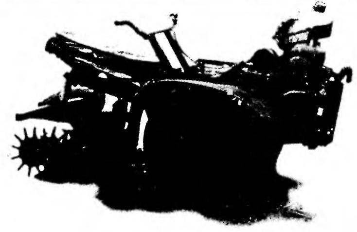 Aim to make brisk, reliable and compact tillers. This mechanical helper and was gardening, and the garden is plowed, and beds cut, and the potatoes on the home field were planted, and seedlings are weeded, and the crop was removed… And most importantly, to run this technique, sitting in a comfortable chair and never feel tired. Not to say that once, but the idea was a success. For three years my homemade motor-block (MB) is, as they say, faith and truth. I called it “Pony.” For endurance, reliability. The only thing he requires is gasoline.