Wing of mixed construction consists of two consoles. The basis of each of the foam core, reinforced with a pair of pine slats-pine spars and trailing edge. The core is cut from a foam block tormaresca made from luchkovoj saws, you only need gear tape-hacksaw to replace the electric current heats the nichrome wire. Cutting also requires a couple of templates cut from aluminum in accordance with the table control section – they are a guide when cutting the foam. The degree of heating of the nichrome wire is chosen empirically using Later: it must be such that after passage of the wire through the foam, it remained smooth, glassy crust. The finished foam core clipped back edge and instead is glued with epoxy resin of the pine rack. Further, on the upper and lower wing surfaces at a distance of 50 mm from the leading edge (30% of chord) are cut with grooves of triangular cross-section under the beam flange. You can use the razor-sharp knife or Bong that is much better, with a special tool, the device which is shown in the figure. Beam flange – pine slats of triangular section to produce them, by cutting on a mini”circular saw” diagonal slats of square section or sostragivaja part of Reiki a miniature plane. Glue shelves are all the same “epoxy”.
From the thus prepared consoles is going to a single wing, which is used for set between the shelves of the spar bridge. The latter is made of two plywood plates with chamfers sawed, glued so that it formed two groove type “dovetail”, which provides a rigorous docking consoles. The rear edge of the consoles glued “on condition”. At least the wing glued two hollow fake ending.
Manufacturer foam core wing:
1 – bushing-insulator (textolite or Teflon); 2 – connection terminal (copper or brass, sheet s2); 3 – a cutting wire (nichrome); 4 – screws; 5 – template (duralumin, sheet s2); 6 – processing core (packing foam); 7 – two-wire cord; 8 – pin (part of the nail); 9 – press luchkovoj saws
Plow for cutting grooves on the core of the wing under the beam flange (bottom right – the use of Struga):
1 – cutters (part of the saw blade); 2 – holder (wood); 3 – base (wood)
The theoretical drawing of the propeller
Trim the foam surfaces, in principle, can only consist in the gradual polishing of the skin decreasing grain size, however, it is better after this surgery primed the foam with epoxy glue, after curing again sanded the surface and painted them with enamel of a suitable color.
Before running the model in the version of the glider should choose the alignment, placing the channel under the rubber motor any cargo. Alignment should be located on a 25 – 30 percent of the length of the SEA wing.
If you run the model it would be cool to swoop down, you should bend the elevators up a bit when you pitch up (climb with the loss of speed) down. The trajectory is properly adjusted models should be a straight downward line. To launch the glider from the rail is required at the bottom of the fuselage to attach the hook from the wire.
For the conversion of the airframe, the plane will need an air screw. Make it from a suitable lime bar in strict accordance with the theoretical drawing. The concave parts of the screw stesyvajut miniature tsiklej or pieces of glass of suitable curvature. After finishing, a screw balance, which fits over the knitting needle, placed on two horizontal steel line. A heavier blade will pull it down, it should soshlifovat skin. Ambulancewoman right screw, if it is to swing must stay on the knitting needle in any position.
The finished screw is covered with several layers of varnish parquet. The screw shaft is curved from a steel wire in diameter of 1,5 – 2 mm. Between the bushing front boss of the fuselage and screw set brass smooth washer.
The table control section of the wing model plane (X, HC and mm – mm)
It is also necessary to prepare a rubber motor. To make it, it between two nails hammered into a suitable Board at a distance of 650 mm from each other, wound round model aircraft tires (its mass should be within 35 – 40 g). On the front and rear ends of the rubber harness with solid sewing threads are made loop under the hook of the screw shaft and the rear hook.
After the manufacture of the rubber motor should be washed with soap and water, dry and lightly grease with castor oil. But between flights and store in a sealed plastic bag.
Adjusting the first flights are made when you twist the rubber motor at 100 – 150 rpm. If the flight model is stable, then the twist of the rubber motor should be gradually brought to full before the second “sheep” along the entire length of the rubber motor.
I. SOROKIN
Recommend to read IN THE CLOUDLESS SKY OF SPAIN Fights over Zaragoza and Wescoe. With the aim of weakening the Franco offensive on the Northern front, the Republican command has taken a series of diversionary strikes in the region of... Sealant? Make it yourself In household practice, a sealing paste known as "Mendeleev's putty" has long been used: it is commonly used to seal the joints of the frame and glass walls of aquariums.
This sealant is... 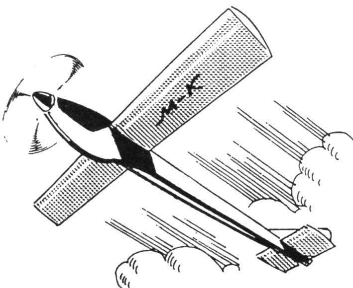
 Schematic model of the airframe and the aircraft, as you know, started flying much earlier than their full-size prototypes. Paving the real aircraft’s path in the sky, they are now helping novice modelers to do their first steps in small aircraft. It is a pity that the modern “schematicity” do not differ from those that did even our grandparents: all of the same pine strips, aluminum wire, model aircraft rubber, a little tissue paper, yarn and glue. No new materials, no advanced design and engineering techniques.