 On the fronts of world war II in the fighting military units along with various armored vehicles involved and light tanks. It is known to our T-26, T-60, T-70, the American M3 and M5, the German PzKpfw I and PzKpfw II. However, the commanders of the opposing sides after some time came to a disappointing conclusion, considering them unfit for action due to relatively weak weapons, and insufficient armor protection. Therefore, in 1943 the production of light tanks was stopped in all countries except the USA, where the M5 was produced in 1944.
However, already in the subsequent peace time, the military of the country decided that the new light tanks in combat was also good for “special and auxiliary tasks” such as reconnaissance, seizure of rear objects in the depth of enemy defenses, cover the flanks of subdivisions, security, performance patrol. Our specialists have put forward an additional requirement to “make a tank floating to ensure amphibious operations.” Meant not only the ability to cross water obstacles, but also participate in operations-planting of river and sea landings, the capture of the island of objects and territories.
Note that the considerable merit in it belongs to Marshal of armored troops P. A. Rotmistrov. After the war he was the commander of armored and mechanized troops in the Group of Soviet forces in Germany, and then in the same capacity he served in the far East. There he encountered a lack of roads acceptable to the redeployment of troops: they were absolutely not suitable for the passage of any wheeled vehicles, not that tanks. To them, if there were bridges, only a small capacity. And, of course, the terrain was a lot of water hazards. So the Marshal said about the need to have in the army armored vehicles, which would be possible to transfer by means of aircraft, including light tanks.
In August 1949, the Council of Ministers of the USSR adopted a Resolution number 3472-1444, which at the Chelyabinsk Kirov plant (ChKZ) was assigned to develop a floating tank under the factory index “Object 740”. The project has also connected the designers of factory No. 112 “Red Sormovo” in Gorky (now Nizhny Novgorod) and Leningrad research Institute No. 100, shipbuilders TSNII-45 im. A. N. Krylov.
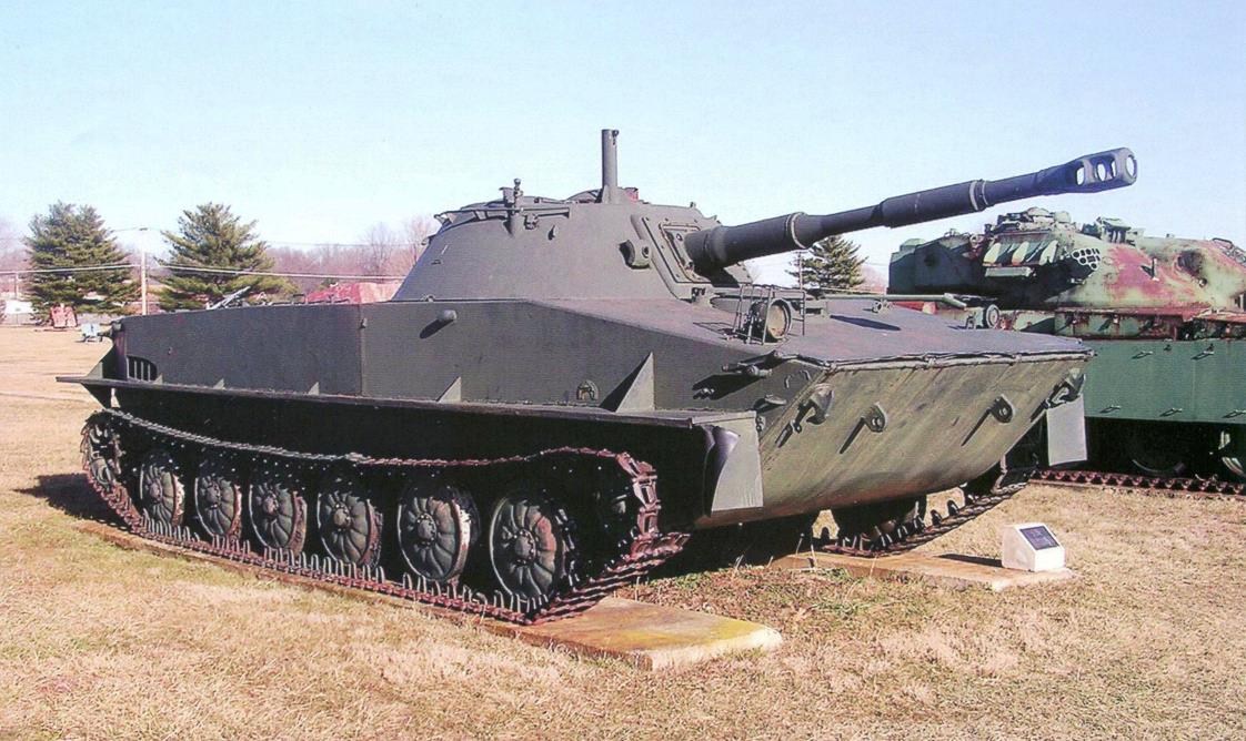
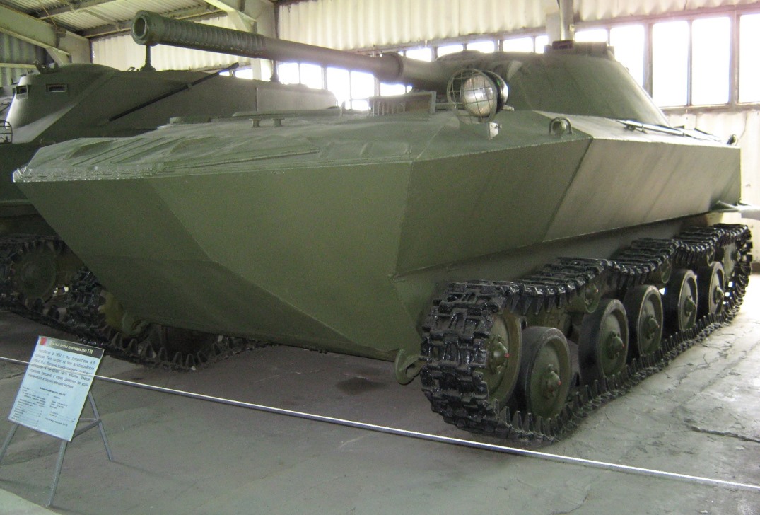
Soviet amphibious tank PT-76 in the Museum at Aberdeen proving ground in USA
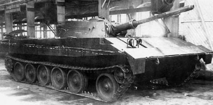
Floating tank project R-39 (“Object 101”) with 76.2-mm gun LB-76T. On the sides of the stacked floats with a light filler. The mass of the tank – 15 tons, 1949
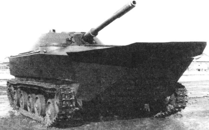
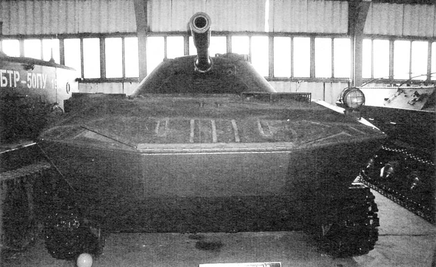
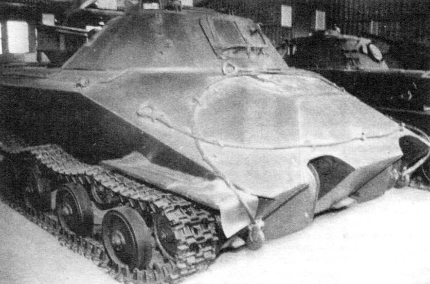
Easy floating tank K-90. Armament: 76.2 mm gun LB-76T, 7.62-mm machine gun SG-43, machine weight – 10.5 t
The technical task was to create a tank weighing up to 14 tons, armed with 76-mm gun, with the reservation of up to 10 mm; operated with a maximum movement speed on land is 40 km/h on water 10 km/h.
How necessary and difficult was this task, evidenced by the fact that at the same time the Special design Bureau of Engineering Committee of Ground forces, A. F. Kravtsov was ordered to duplicate the project under the designation K-90.
Such a serious ‘double’ attitude towards the project was caused by the failure to establish in the late 1940s, a whole line of light tanks. The last of them – an the P-39 was filed in the summer of 1949 to the test, but because of the significant problems was not accepted by the acceptance Commission with the conclusion: “experimental tank samples do not correspond to the approved specifications and consequently are not suitable for the Armed forces.”
Originally a project of this tank under the designation PT-20 began to develop on the plant “Krasnoe Sormovo” in 1947 On the machine planned to install an 85 mm gun, armor protection from 14.5 mm bullets, diesel engine capacity of 400 HP and not to go beyond the limits of the 20-ton combat weight. In addition, developers have proposed several strange even at that time the decision (apparently, in accordance with some foreign models) to provide machines to improve special buoyancy floats filled with light filler. They had to be removable and be carried separately on trucks following the tanks. However, consistent with common sense – difficulties not only their delivery but also application in the field, especially under fire of the enemy, the military command has not made such a decision.
The consequences are not forced himself to wait – there has been a change to the technical requirements. The need to “implement their own buoyancy” forced to reduce the combat weight up to 15 t, to put a smaller motor power up to 300 HP and lower caliber guns up to 76 mm. This was an updated draft of the P-39.
Two new sample project under indexes “the Object 101 and Object 102” prepared by may 1949 It was a car with bulletproof plating 12-mm armor plates, turret with 20-mm armor, armed with 76.2-mm cannon LB-76T, specially designed by the designer A. Savin in the Gorky KB No. 92. They were delivered with derated engines and transmission from T-54.
Afloat the machines worked two propellers. The “Object 101” they were in the tunnels of the bottom, had a diameter of about 350 mm and greater speed. “Facility 102” screws assembled with swivel handlebars, they were a larger diameter, 600 mm. But the two samples you are testing out the speed afloat no more than 7 km/h, which was only 50% of the required task.
Propellers constituted one of the main problems of project P-39; it applied not only to the choice of their external characteristics (diameter, pitch, rotation speed), but also to their location, which had to attract shipbuilders. So, to increase the speed on the first sample decided to increase significantly the diameter of the screws, but because of this, they had to endure from the tunnels, and that they do not interfere with the traffic on the roads – to make lifting. I did the same with the second sample, also had made the screws, the movement by land was very difficult. In addition, this arrangement of propellers at the stern required installation of additional protection for them.
Another problem is the trim and the roll housings on the water. To eliminate them, resorted to the move of the tower, the welding of steel plates in the bow. The buoyancy tanks could provide, still put the removable steel floats with a light material, similar to the current foam.
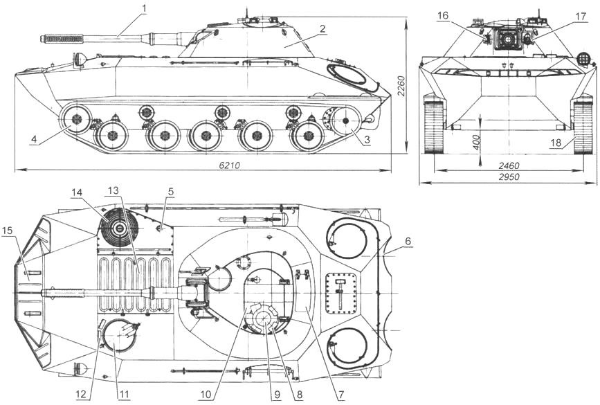
Easy floating tank K-90:
1 – 76.2-mm gun LB-76T; 2 – turret; 3 – driving wheel; 4 – driven wheel; 5 – hatch bilge pump; 6 – a niche of the propeller; 7 – escape hatch; 8 – observation instrument of the commander; 9 – commander’s cupola; 10 – closed turret hatch; 11 – driver’s hatch; 12 – viewing device of the driver; 13 – armored louvers of the engine; 14-cooling fan; 15 – balneotreatment flap; 16 – loophole 7.62-mm machine gun SG-43; 17 – loophole sight TSHK-9; 18 – track chains
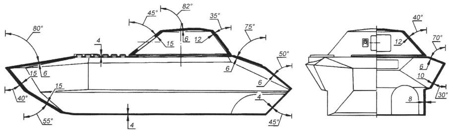
The forward part of the tank hydrodynamic streamlined shape with sloped frontal armor plates and the big island. The armor thickness of 15 mm
Scheme of armor protection of the tank K-90
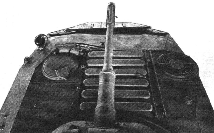
The front part of the roof. Front laid balneotreatment flap on the left side – the driver’s hatch, on the right – the cooling fan on the center – armored louvers of the engine compartment
However the taken measures have not given life-saving results: the design of the tank R-39 was closed. Began a new phase of the light amphibious tank -including under the designation K-90.
Special design Bureau of Engineering Committee (OKB IR SV) was formed in 1947 at the Moscow Military repair plant No. 2, with the Main armored management (SAS No. 2, gbtu). For the position of chief of the Bureau was appointed in 1948, a military engineer A. Kravtsov (1951 chief designer).
The order of the Minister of the Armed forces of Marshal A. Vasilevskiy from 9 December 1947, it was noted that CB was created “… for the rapid testing of tracked amphibian designed for the crossing of artillery and tanks in crossing rivers.” A. He then worked to develop a floating conveyor for the delivery of personnel and military cargo. In the beginning of that year he presented to the leadership of the Land forces new technical solution to a self-propelled desantirovanie tools that received a positive rating.
The amphibians expected to use the basic aggregates production artillery tractor M-2, then produced at factory No. 40 in Mytishchi near Moscow. Exploring the layout, the designer has established, in particular, the location of the engine-transmission compartment under the cargo area, the feasibility of the use of the rear wheels using a pair of propellers, the prisoners in the tunnels of the bottom aft, the calculated parameters and ratios of dimensions. The results of their research A. Kravtsov, and laid the basis for the design of a floating tank.
The layout of the compartments, differed originality. The engine with system of implementation, the bow was shifted to the starboard side, so the left front was the control module, the transmission mechanisms housed together with cardan shafts, held back through the whole body along the median plane. Fighting compartment with a tower was designed in the stern.
The housing of the hydrodynamic streamlined had two frames, five rear torsion beams and power beam. Welded together from rolled armor plates installed under rational angles. The upper face sheet due to the large angle of inclination equal to 78°, had a small thickness of only 8 mm, but the main face and leaves the cheeks set at angles 40° and 35°, there was a significant 15-mm thickness; the side was less protected, components of the upper and lower leaves had a thickness of 10 mm and 8 mm, respectively; at the stern, the roof and the bottom put the 6-mm armor.
Front left in the hull were the driver’s hatch, skryvavsheysya swivel cover, right there bronejilety of the fan and the outlet, in the middle of the Central part – the hatch over the engine with the armored hoods for the passage of cooling air and the hatch bilge pump.
Three-piece balneotreatment the front flap installed in the eyelets of the bow was removable.
The car set 4-cylinder diesel engine yaz-204 power 140 HP at 2000 rpm, two-stroke with liquid cooling. To facilitate engine start at low temperatures it provided a heater; in the lubrication system applied oil-water radiator, air cleaning system – air purifier with a set of cyclones.
The issue of engine yaz-204 was started in 1947, But earlier – at the end of 1941 – at the Yaroslavl state automobile plant No. 3 in order to more rapid production of new trucks needed engine GMC “4-71” produced in the United States. They were requested under lend-lease; they arrived in Vladivostok and stayed there until 1943, But since there were only fifteen hundred, in Yaroslavl has created a replica engine under the symbol yaz-204, a few modified. These engines were installed not only on the well-known trucks yaz-200, but on artillery crawler tractors I-12.
By the way, the production of these tractors in Yaroslavl closed in 1946 the Production was transferred to factory No. 40 in Mytishchi, where in September 1945, he was produced a pilot batch under the M-12A. In 1948 they were replaced by modified tractors M-2, which was in mass production until 1955
It is no accident, the chassis was borrowed from the towing vehicle M-2. She was well developed for the installation of the SU-76M and moved along with the rollers, sprockets, rocker arms, torsion bars, tracks. The car was five planar supporting rollers with a diameter of 500 mm on the side and three support, idler with tensioning mechanism – front sprocket – feed; track – melkosofta width of 300 mm.
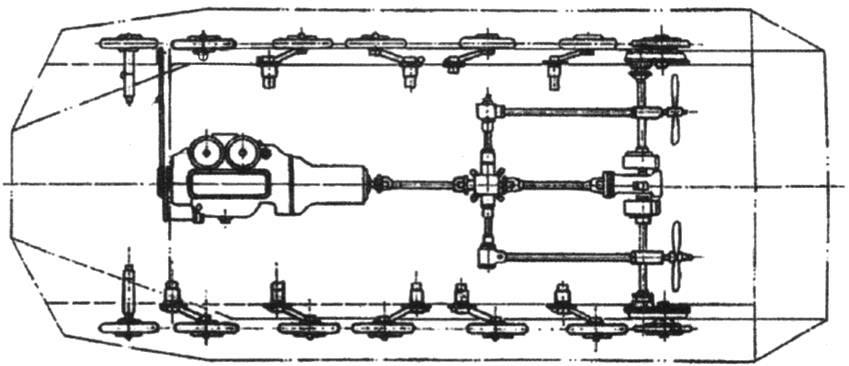
Scheme of transmission tank K-90
Feed tank: the bottom of the visible niches of the propeller; in tank turret rear escape hatch
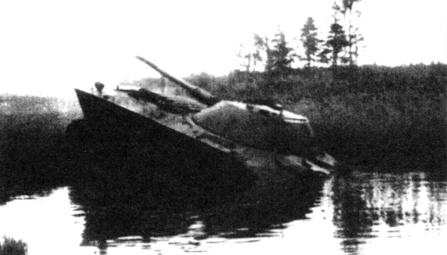
The output of the tank on the shore. Test 1950
Transmission at the K-90 was held under the stern crew compartment. It had a single-disk main friction clutch, transfer case, main gear, two boxes reverse propellers, steering clutches, from cars yaz – 200, M-20, from a Prime mover M-2 was used five-speed gearbox, driveshafts.
During the project development before the designers was a choice of propeller speed through the water from several options. The car could move, for example, by rewinding the tracks, having propellers of different location – in the tunnels or on the stern, but then they would have to make retractable in order that they not interfere with the movement by land. It would be possible to put a water-jet propulsion, but it was used by the developers of “Object 750”.
A. Kravtsov K-90 has placed the propellers at the stern of the hull in the niches of the bottom. They were rotated using the power takeoff conical reverse, and the clutch switch was not a neutral position. This led to the fact that afloat at the same time worked and propellers, and the caterpillar, adding speed. The diameter of the bolts was 600 mm.
Turning the handlebars were installed with screws in an output stream, which contributed to more effective action. While they made a composite of two halves that can close niches of the body. Thus, a cover of propellers from damage when moving the machine, especially on rough terrain.
Aft of the K-90 on the body was the battle tower, conical in shape, welded from bent armor plates with variable angles from 35° to 45°. The frontal part of the tower was 15 mm thick, sides and stern – 12 mm. On the roof of the tower on the left had a small commander’s cupola with observation devices, in the right side – the exit hatch in front of him fan with bronenakladkoy. In the aft wall of the tower was set the door of the escape hatch.
Service K-90 76.2-mm gun LB-76T and coaxial 7.62-mm machine gun SG-43, located on the right. The length of the barrel of the gun – 46,1 klb.
The shooting was carried out using a telescopic sight TSHK-9, which was placed in the left embrasure of the tower. The turret weapons range from – 4° to +25°.
Gun loading is done manually, the rate in this case was 6-7 RDS./min. Ammunition, which had 40 shots and 1,000 7.62 mm ammo laid out on the floor of the fighting compartment around its perimeter.
The crew consisted of three people. The workplace of the commander, simultaneously acting gunner, was left of the gun; he could observe the terrain and the battlefield through glass blocks on the tower and observation instrument MK-4. The loader is located to the right of the gun. The driver’s compartment were used for the closed hatch two prismatic devices.
Experienced light floating tank K-90 was created in early 1950, and passed the test program. By this time, was prepared and samples of “Object 740” Chelyabinsk Kirov factory. Therefore, the order of the USSR Council of Ministers from 5 to July 29, was assigned to their comparative tests with overcoming water obstacles and various obstacles. “Object 740” showed the best vodorodnoe quality; the Commission remained dissatisfied with the unreliability of transmissions and propulsion K-90. However, probably the most pernicious was the test tank to jump into the water. The fact that competitors-the players proposed a fee to show their cars to new levels, based on the fact that their car is superior to another for some specific indicators. So, the developers of “Object 740” suggested testing machine to jump into the water with a four-meter coast slope at full speed. K-90 entered the water well, under the “reliable nose trim”, but then lurched to the stern, quickly began to draw water and went to the bottom. The crew managed to get out of the car, though not without difficulty. Then it turned out that the hatch bottom just was not capped, what was the water filling the housing. However, the next test was with the noise lost that and had a corresponding impression on the Committee. As a result, the discussion was followed by a competitor, which was adopted under the designation PT-76.
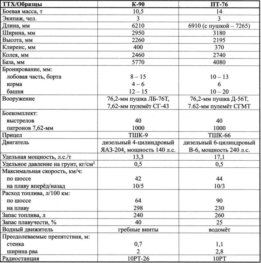
PERFORMANCE CHARACTERISTICS LIGHT amphibious tank K-90 and PT-76 (“Object 740”)
At the same time, noteworthy is a comparison of some characteristics of prototypes. So, the mass of the K-90 was almost one and a half times smaller, the buoyancy exceeded twice. On the tank stood a standard engine trucks yaz-200 with 140 HP, a competitor – an expensive tank of V-6 rated at 240 HP On the K-90 was used components and assemblies of the chassis of the tractor M-2 – “object 740” chassis re-created. The development of machine A. Kravtsov cost 30% cheaper.
The development of the tank K-90 was practical stepping stone to create widely known in army units floating crawler Transporter K-61, adopted by the Soviet Army on 16 may 1950 For his great contribution to the problem of creating and equipping of the Soviet Army crossing means the initiator and Director of A. F. Kravtsov in 1951 he was awarded the Stalin prize.
V. BORZENKO
Recommend to read
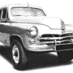 GAZ-M72 Pobeda
In 1955 the designers of the Gorky automobile plant (GAZ) on the basis of units of army SUV GAZ-69 and the body has just launched a series of "Victory" GAZ-M20 has created a comfortable...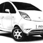 TATO NANO
Tata Nano is a ultra-small city car produced by the Indian company Tata Motors — the stated price is only $2500, making it the cheapest in the world. The capacity of this vehicle is...