 Bomber XB-70 VALKYRIE. The first jet bomber the BOEING b-47 came to the command of the U.S. air force in late 1951. However, the aircraft with maximum payload of about 10 tons could carry in their sections, not all types of bombs from the nuclear Arsenal of the United States at the time and thus became just a huge addition to the piston b-36. This circumstance was the cause of the development of the heavy bomber b-52, the first modification which was twice higher than the b-47 take-off weight in the range of about 5500 km, and, most importantly, could carry a hydrogen bomb MK.17 weighing 21 tons with a TNT equivalent of 20 megatons.
The emergence of Soviet antiaircraft missiles and supersonic interceptors questioned the possibility of achieving targets in the depth of USSR subsonic bombers. Therefore, in 1954, the U.S. air force gave Convair a firm order for building the supersonic b-58. With European bases, these aircraft were the first to invade Soviet airspace and strike at key air defense sites, opening the way for the heavy b-52. However, the strategic air command is not too low in relation to the b-58 because the aircraft without additional fuel had a small range (about 1500 km), and frequent accidents thoroughly undermined his reputation.
At the end of 1954, the commander of the strategic air force, U.S. air force General Le may has applied to the Ministry of defence with the request to consider the creation of another aircraft to fully replace the b-58, with a flight range without refueling in the air for at least 11 000 km and a speed corresponding to the number M = 3*. Such aircraft, for operation of which would fit the existing airfields and facilities, planned to be armed with the U.S. air force from 1965 to 1975.
By order of Lemay the U.S. air force has produced a document COR No. 38 — “a Common tactical requirements for a manned bomber Intercontinental bomber weapon system”. After some time there appeared another document, in which the aircraft project was given the designation WS-110A “Weapon System 110A”. Diagram of combat use of the bombers was approaching the target at very high altitude at a speed corresponding to the number M = 2, increase it to M = 3 in the target area. Then followed the attack of the object guided missile of class “air — land” with nuclear warheads tion, after which the bomber had a maximum speed removed from the target area.
At the suggestion established in April 1955 in Litovskom research center group to study ways of implementing these requirements, the chief of staff of the U.S. air force ordered the development of the project WS-110A on a competitive basis among the six American firms. The main condition of victory in the competition was to achieve the maximum possible height and speed of flight over the target. Deliveries of production aircraft to the strategic air command scheduled to start in 1963.
The company introduced the air force its proposals in October 1955. Next month companies Boeing and North American have issued orders to conduct the design studies of the aircraft. It should be recalled that at that time due to large fuel consumption, long flights at supersonic speed styles limited the variety of supply of fuel. Therefore, both project included the creation of an aircraft for WS-110A with a huge size and weight.
Thus, the firm North American designed a 340-ton aircraft with a wing composed of a trapezoidal center section and a pair of consoles with a reverse sweep. In the area of their dock located fuel tanks, holding 86 tons of fuel and provide Intercontinental range with a large subsonic speeds. The target console with the tanks were dropped, and the plane to throw to the target and follow-up care was accelerated to the speed corresponding to the number M = 2,3.
About this project the General Le may sarcastically remarked: “It is not a plane, and a flight of three aircraft.” To all, to maintain such a huge bomber using existing airfields and ground equipment was impossible. Both of the presented project was rejected, and shortly thereafter the development of a weapon system WS-110A limited only to research the possibility of creating such an aircraft.
In 1957, Boeing and North American submitted a new project proposal for WS-110A. Independently from each other, they came to the conclusion that using high-calorie synthetic fuels can achieve supersonic cruise flight speed without the need for exotic layouts. In addition, the development of the theory of flight have significantly improved aerodynamic quality heavy machines that reduced the amount of fuel needed to achieve Intercontinental range flight at high speed.
In studies of particularly successful firm North American decided to use in your project new principle of increasing lift force developed by NASA. She held a series of wind tunnel, in which it was found that aerodynamic efficiency is significantly increased due to the additional lifting force created by the shock wave. Based on this principle, very similar to the effect of planing speedboats on the redan, it is possible to create an aircraft that meets the requirements of the air force, regardless of the type of fuel used.
In the late summer of 1957, the U.S. air force, intrigued by these results, to extend the program of research so that firms have presented projects with a description of the main systems. After evaluation of works by the specialists of the air force in December 1957 there was a preference for project bomber XB-70 VALKYRIE (“Valkyrie”) of North American, which signed a contract for the construction of 62 aircraft: 12 experimental and pre-production and 50 directly to the air force. In parallel entered into with General Electric company a contract for the J93 engine, capable of working both on conventional and synthetic fuels. The entire program was estimated at 3.3 billion dollars.
Part of the necessary scientific research was planned in the framework of the test range interceptor F-108 “rapier” with the same engines J93, which could reach the speed of 3200 km/h and was armed with three guided missiles with nuclear warheads. The radius of the F-108 over 1600 km and ferry range of the aircraft reached 4,000 km. “Rapier” was intended to protect strategic assets from Soviet bombers, similar to “Valkyrie”, whose appearance on the arms of the Union are not forced to wait long in the case of acceptance-70 on Board.
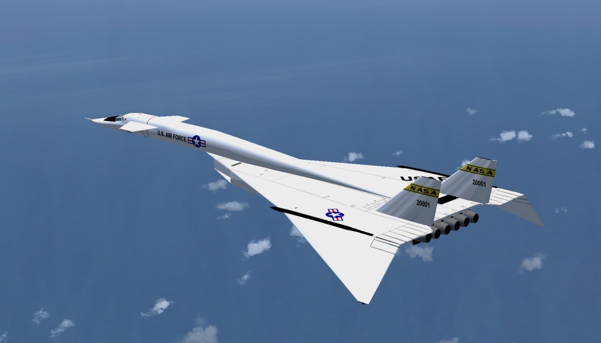
XB-70 in flight. Visible bent the wing tips
The USAF insisted on the acceleration of the development program aircraft In-70 to its first flight took place in 1961 (18 months ahead of schedule) and the first wing of 12 aircraft could be established by August 1964. The first phase of the program is to develop, build and approval of the layout of the aircraft — planned to complete by March 1959.
In March and April 1959, the air force specialists carried out inspection of the project and the construction of the mock aircraft. It was proposed to make 761 a change in the project and 35 changes in the layout. At that time, the program of development of the b-70 was a priority. However, this did not last long.
The first failure in the program was associated with high-calorie fuel for engines J93 based on compounds containing boron and hydrogen, the so — called brovedani fuel. It certainly had a greater calorific value than kerosene, but the use of it did engine exhaust is poisonous, causing all ground staff to work in a state of permanent chemical warfare. In addition, the cost broadridge fuel was very high and according to calculations by burning it in engines J93 flight range was increased by only 10 percent. This increase was considered insufficient to justify the cost of development and manufacture of new fuel. Even despite the fact that the construction of the plant for its production was almost finished, program development broadridge fuel stopped, and the plant cost 45 million dollars and has not been fired.
A month later and stopped the development of supersonic fighter-interceptor North American F-108, engine borodaruda fuel.
In December 1959, a programme of development-70 reduced. The new plans called for construction of just one bomber XB-70 without sighting and navigation and other combat systems. The first flight was scheduled for 1962, and flight tests was extended until 1966.
In the summer of 1960 in the Moscow air parade in Tushino was demonstrated bomber M-50, designed by V. M. Myasishchev. A formidable fighting is a kind of new machine shocked foreign military delegations. Not knowing its true flight characteristics, the Americans immediately resumed the program of development of “Valkyrie” in the same volume. But in April 1961 the new Secretary of defense Robert McNamara, a big supporter of the missiles, calmly scaled it back to build three experimental bombers. At this time, “Valkyrie” has survived only due to the fact that it can be used as a carrier of the Skybolt missile, which was developed by the firm Douglas.
In January 1962, in response to another threat of closure of the program WS-110-And again changed, and the aircraft received the designation RS-70 — strategic reconnaissance-bomber. The revised program included the construction and testing of three prototypes. The first two only research — had the designation XB-70A, and the third (XB-70V) with a crew of four(two pilots, an operator of electronic warfare systems and co-driver) was designed to test combat systems.
In March 1964, the program was again reduced, it was planned to conduct flight tests of two prototypes, the XB-70A. The US air force began to seek all possible and impossible means to return To-70 to life as a military aircraft, stating that it can be used as a supersonic transport aircraft that are stored starting stage combat spacecraft, such as “Dinosaur”, and a platform for launching ballistic missiles. Even has been suggested that he may perform the functions of a space interceptor, and the force was reason. Experiments on the interception of satellites began in the late 50-ies and was very successful. For example, 13 October 1959 with the b-47 launched a rocket of WS-199В, which flew six kilometers from the “target” satellite, located 230 km from the earth’s surface. If the missile had a nuclear warhead, the satellite would have died from an electromagnetic pulse.
Despite the shortages of funding and ongoing debate in the Congress not promised the fate of the plane, nothing good, firm North American was built a prototype of a Valkyrie.
The XB-70 had the aerodynamic scheme “duck” with a triangular wing and trapezoidal canards. Maximum takeoff weight of the plane was 11 percent more than the b-52, and the length dimensions of the Pitot — 3.3 m more. The ends of the Delta wing in cruising flight, is deflected down to increase directional stability and reduce the resistance from balancing at the speed of flight, corresponding to the number M = 3. To control the vehicle in roll and pitch was used elevons. The cockpit was at the height of 6 m above the ground. In a large bomb Bay with a length of almost 9 m, located between the inlet channels, it was possible to place a nuclear bomb of any type. Bomb Bay was closed with a large flat sliding panel which when opened slid back.
The first prototype XB-70A was calculated for the two-man crew. Thanks to the powerful air conditioning system and sealing members of the crew wore only a lightweight flight suit and helmet with oxygen mask. It provides freedom of movement and relative comfort, which was not on other high-altitude and high-speed aircraft. For example, the crew of the high-speed F-12 (SR-71) was forced to fly in spacesuits from the space ship “Gemini”, and the pilots high-altitude U-2 in special suits and pressure helmets.
Plane XB-70A established six turbojet engines J93-GE-3 of the General Electric company, developing with the included afterburner thrust about 14 060 kg each. Positive static pressure behind the shock wave formed at the front edge of the wedge of the intake, worked on the lower surface of the fuselage and the wing and create additional lift. This allowed the aircraft to perform cruise flight with small angle of attack and therefore minimum drag. The inlet was divided into two channels of rectangular section with the wedge having a height at the entrance of 2.1 m. the Length of each channel, the supply air to the three engines, about 24 m. the air Intake is adjustable.
Shocks arising in the ordinary canopy, dramatically increase the drag, which is unacceptable in flight at a speed corresponding to the number M = 3. At the same time when landing, it is necessary to provide the pilot a good review. Firm North American chose a relatively simple method of satisfying both requirements: the surface of the sock of the fuselage in front of the windshield yourself windshield is made movable. In flight at low speed they fell, providing visibility ahead, and in supersonic flight raised, forming m
tion transition of the bow in the fuselage. Subsequently, approximately in the same way I solved this problem the designers of passenger aircraft, the Concord and Tu-144, and an experienced bomber Sukhoi T4 (ed.”100″).
The design of the XB-70 made of steel and titanium were calculated on a long flight with a speed of over 3000 km/h when the cladding temperature to 330 °C.
An even more important moment in the history of “the Valkyries” than the use of new materials was the transition from riveting and Assembly manual for soldering and welding of aircraft structure, which is comparable with the same revolution in shipbuilding, where separately collected compartments and welding have replaced the infinite number of rivets. In the factory building, where they conducted the Assembly XB-70, could only hear the hiss of a dozen welding machines, replacing the traditional pneumatic hammers and pneumodrive, and the sound of milling heads, Stripping weld seams. In some places of the structure where no riveting to do was impossible, to save weight used tubular rivets.
Problems in the design of the XB-70 was so much that North American could not cope with them, and part of the work transferred to other companies, which number over 2,000. The largest host wing — is made firm, Boeing.
When it was manufactured and delivered to the Assembly shop, it turned out that it does not fit with the fuselage. With great difficulty he managed to weld manually. Thus the continuous length of the connecting weld has reached 24 m. Separately connected to the upper and lower wing skin. The wing spars with ribs of the fuselage welders have docked a lying on the wing through the slot in the casing, which is subsequently closed by a cover.
During the design of the aircraft is very widely used computers. Especially on the firm Boeing, which only through this can catch in time with her substandard wing.
The first XB-70A was built with a delay of a year and a half. Only on 11 may 1964 the aircraft was ceremonially rolled out of the Assembly shop. At the ceremony devoted to this event, the Director of the program of production of the XB-70 General Fred George.Scully presented the prototype of the bomber to the press.
The first flight was scheduled for August 1964. The company wanted three months to verify all systems are unique machines. In fact it took her almost five months. Another prototype XB-70A at this time was almost fully assembled fuselage and wing center section. In the fuselage nose installed aircraft systems. Circled the second car was scheduled for the end of 1964. The main difference of this prototype was small transverse V-wing (only 5°). The angles of deflection of the wing panels was increased by 5°.
During the last phase of ground tests were finally worked out a responsible procedure of the fuel. The average gas station “Valkyrie” lasted half an hour. First the fuel was pumped from one tanker in the second blank, which in the meantime was served dry nitrogen under high pressure; nitrogen was purged through the fuel filling mouth and replaced the oxygen. Thus, the fuel flowed into the tanks so inert (explosion proof) how this can be achieved in the field. The fact that the fuel was used as a chiller of some systems of the aircraft and its operating temperature in air up to 1000 °C. If the content of oxygen in the fuel would exceed the norm, then it would start to oxidize and broke. Thus, if “Valkyrie” to fill a traditional way, the plane could just explode in the air.
For flight testing the XB-70, the firm has produced two of the crew. At the head of each there was an experienced test pilot of the firm, and the co-pilot was a representative of the air force. The primary crew was led by pilot ell white, the second pilot — captain John Kopton. The doubles was John Sebe and Colonel Fetu Fulton. The flights were planned to carry out over the sparsely populated areas, extending from Edwards air force base to the Utah.
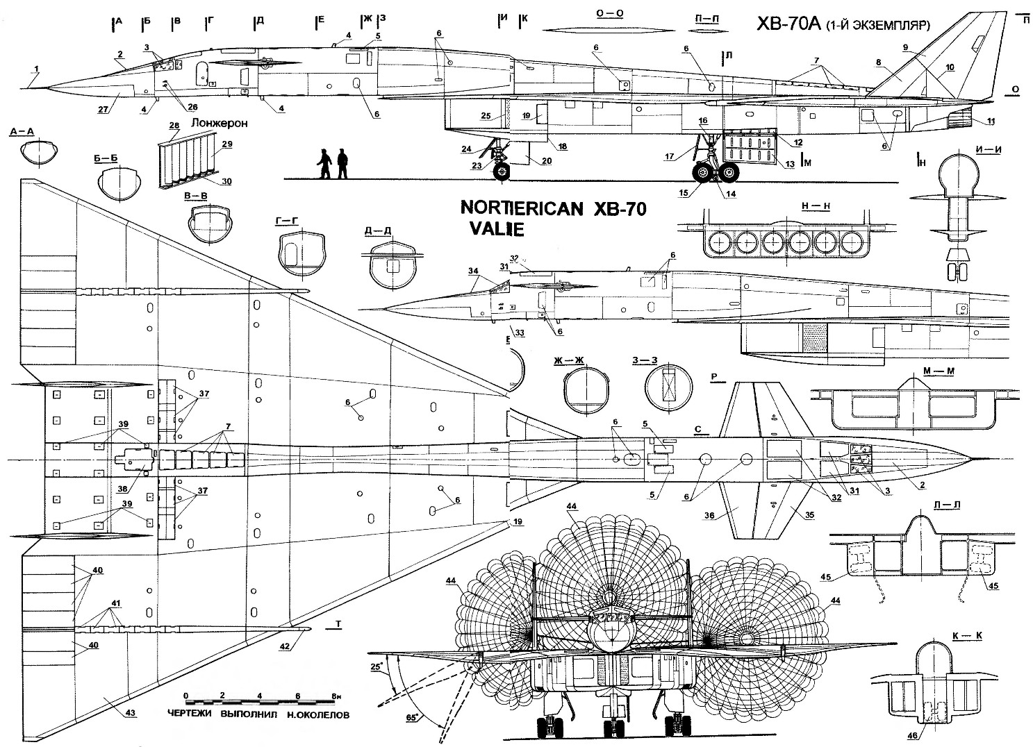
![Experimental supersonic bomber XB-70]()
Experimental supersonic bomber XB-70 “Valkyrie”:
1, the receiver air pressure (LDPE); 2 — retractable ramp; 3 — an external movable windshield; 4 — rod antenna a VHF radio; 5 — sash ropes of air discharge from air conditioning system; 6 — removable maintenance hatches; 7 — hinged maintenance hatches; 8 — keel; 9 — rudder; 10 — axis rudder: 11 —adjustable nozzles; 12 — niche cleaning truck main landing gear; 13 — fold niches main landing gear; 14 — wheel of the machine release; 15 — heat-resistant pneumatic wheels main landing: 16 — main landing gear; 17 — flaps main landing; 18 — crack a reset of the boundary layer; 19 — antisurge fold; 20 — fold truck niche nose landing gear; 21 — cylinder retract-front; 22 — front wheel; 23 — the front landing gear; 24 — the shield-front; 25 — adjustable wedge air of kasabonika, punched for suction of the boundary layer; 26 — additional LDPE; 27 — radionotes NY radar Radome; 28 — the regiment of spar; 29 — corrugated web spar; 30 — welds; 31 — emergency hatches of prutow; 32 — emergency hatches of the operators of weapons; 33 — door; 34 — ramp and external glazing in the retracted position (takeoff and landing); 35 — adjustable horizontal tail (stabilizer); 36 — elevators (flaps); a 37 — fold intake of the secondary air cooling the engine; 38 — brake panel — hatch compartment brake parachutes; 39 — hatches access to the fixing points of the engines; 40 — section Aileron; 41 — the hinges of rotation of the wing tips; 42 — fairing of wing hinge point formation of vortex flow around the wing; 43 — deflected wing tip; 44 — brake parachutes; 45 — truck main landing gear in the retracted position; a 46 — truck the front landing gear in the retracted position; 47 — the toe of the rudder sandwich construction with honeycomb core; 48 node panels connection; 49 — fasteners; 50 — spar of the rudder; 51 —the tail cone of the rocket (if the suspension in the bomb Bay was not established); 52 — roller shutters-chamber arms; 53 control equipment on-off ramp and glazed; 54 — dashboard; 55 — inner panel windshield; 56 rescue capsule; 57 — parachute; 58 units of electronic equipment 59 — tanks with liquid ammonia and water; 60 — electronic equipment control system, recorders registration overload from wind gusts: 61 — air conditioning system air ha in the cockpit; 62,63,66,69,72 — fuel tanks; 64,65,67,71,83 — spars of the wing; 68 — pylon suspension of missile; 70 units weapon control; 73 — power beam; 74 — installation of a braking parachute; 75 — frames; 76 — YJ93 engine; 77 — box actuators of the engine; 78 — the air intake duct; 79 — a guided missile XGAM-87A Skybolt; 80 — armament Bay; 81 system data logging, digital and analog calculators; 82 — truck niche nose landing gear, 84 — cockpit; 85 — equipment operator arms; 86 — the operator’s arms (at the experimental aircraft were used to accommodate electronic equipment), 87 — thrust weapons; 88 — blocks radar; 89 — radar antenna; 90 — the hinges of the rudder; 91 — tandem actuators of the rudders; 92 — binder thrust: 93 — spring loading mechanisms of the control system; 94 — spring thrust; 95 — hinges hinge elevons; 96 Titan panel; 97 — actuator elevons; 98 panel wing skin cell structure; 99 — mount actuator elevon; 100 — hydraulic cylinder Elevator deflection (landing flaps); 101 — the cylinder of rotation of the horizontal tail; 102 — sliding panel to be fitted; 103 — fairing niche nose landing gear, 104 — deflected wing tip; 105 — the hinge of rotation of the wing tip; 106 — actuator fitting ending; 107 end rib of the wing; 108 control wheel in the working position; 109 — double-doors-blinds capsules; 110 — stick ejection system; 111 — the control wheel at ejection
In 8 hours 38 minutes 21 September 1964 the plane, operated by white and Cotonou, taxied at the start, and white requested permission for takeoff. The XB-70 was supposed to fly to the base of Edwards. During the run he was accompanied by two helicopters of the rescue service, and in-flight double T-38.
Even with one T-38 the cameraman was filming everything that happens with “Valkyrie” in the air.
The nose wheel “Valkyrie” off the ground at speeds of 280 km/h and the car began to gain altitude. However, to remove the chassis failed: the front Desk went fine, but the main only half. Had to lower the landing gear and return to the airfield. After some time, he denied the fuel control system of one of the six engines. But this aerial adventure XB-70 is not over. The biggest trouble was expected by the crew during touch the ground. Brake discs left landing gear was stuck, and caught fire from the friction of pneumatic wheels. Throughout the two-kilometer mileage for the car trailed black smoke from burning rubber. After stopping the aircraft the fire was extinguished and the car was towed to the hangar. The first flight lasted 60 minutes.
To eliminate defects gone for two weeks. During the second flight in the support group included the supersonic b-58. Landing gear removed without comment, but the surprise came from the hydraulic control system. A small crack in the tube at an operating fluid pressure of 280 kg/cm2 led to a reduction of pressure in the system and switchover to the backup channel. Despite this, the plane made it to Edwards and landed on one of the runways.
October 12, 1964, in the third test flight of a duration of 105 minutes, the first prototype of the “Valkyrie” reached an altitude of 10 700 m and for the first time broke the sound barrier, speeding up to the speed corresponding to the number M = 1,1. From the aircraft maintenance noticed how at the moment of crossing the sound barrier with some parts of the plane the vibrations came off the paint and the XB-70 after planting had a very shabby appearance.
In the fourth flight, on 24 October 1964, at an altitude of 13,000 meters first turned on the control system of the wing tips and brought in the afterburning mode, all six engines. The pilots were pleased with the aerobatic qualities of a unique aircraft — the Valkyrie is easily managed and behaved steadily.
Fly the second prototype took place on 17 July 1965. A little later, October 14, 21 at a height of 335 meters XB-70 reached a speed corresponding to the number M = 3. The duration of the flight at this speed should have been on the program for 5-6 minutes, but within two minutes the pilots heard a loud noise and turned off the afterburner. The cause of the noise turned out only after the landing. It turned out that the section of skin the size 0,9×0,3 m sock left wing, near the external air inlet of the engine was broken in flight. By happy coincidence this piece of skin has not got the engines. The inspection of the aircraft after the flight showed that the curved trim panel moved to the welded seam and broke, without damaging the honeycomb. The car repair took one day, and testing continued.
June 8, 1966 flying the XB-70 was suddenly interrupted — he crashed the second prototype. This day was planned to film his flight, accompanied by several fighters on film for advertising the film. In 8 hours 27 minutes in the morning to the cabin occupied by E. G. white and major K. Cross. In the air to the bomber were to join the two aircraft T-38 and F-4 (Navy) and F-104 (air force). The F-104 was flown by experienced test pilot of the firm’s North American John Walker, who had just finished flying at hypersonic X-15 and had to go to the XB-70.
An hour later, when the aircraft breaking through the cloud lined up for shooting, F-104, flying to the right of the 70th, touched its wing lowered wing tip of walküre, flipped over the fuselage of the bomber, beating him in both of the keel, hit the left elevon and exploded. A few seconds Valkyrie continued straight flight, as if digesting what happened, then flipped over the wing, went into a tailspin and fell. Survived Ella white, who managed to catapult his capsule before the fall. Him lying on the ground the parachute were spotted by a rescue helicopter a few kilometers from the wreckage of XB-70. The landing capsule with half-opened parachute was very rough, white suffered serious injuries and three days did not come to consciousness. The bomber is little left nose part in which there was a Cross, ripped into several pieces. Likely, the car exploded in the air. Ell white recovered, but never flew.
After this tragic event, the remaining flights of the first airplane continued for another two years. In total, he has completed 83 of flight. In 1968, work on In-70 was discontinued. On 4 February 1969, Valkyrie took off last time. The machine is controlled Feet Fulton from North American and Those Tenfold from the air force. The XB-70 landed at the air base Wright-Patterson, and became a Museum exhibit of the air force. During the transfer of the aircraft to the Museum one of the pilots said he was “…I agree that the “Valkyrie” continued to fly, but not willing to pay for flights”. And the XB-70 was in the Guinness Book of aviation as the world’s largest research aircraft.
Dry weight of the aircraft the XB-70 was 68 T. Design forward fuselage with a length of about 18 m was a siding with reinforcing elements. For its production used items with a total mass of 5440 kg of the three brands of titanium alloys; in particular, for plating was applied sheets of titanium alloy with a thickness of from 0.75 to 1.78 mm. This choice of materials stems from the fact that the cladding temperature in flight could reach 220-260 °C.
The crew of the combat aircraft b-70 was to consist of four, located in pairs behind each other in front of the cabin. The cabin is separated hermetically closed by a partition into two compartments. Along the axis of the cockpit in the middle there was a passage leading into the compartment electronic equipment. For thermal insulation of the cabin was used fiberglass.
In normal flight the air conditioning system was supported in the cockpit and in each of the compartments temperature 21 — 27 °C and the pressure corresponding to the pressure at an altitude of 2400 m. the temperature of the cabin walls did not exceed 24 °C due to run air through the porous insulation between the walls and the fuselage skin. Air conditioning system was very important, because its failure in flight at an altitude of 20 000 m would lead to the death of the crew. In the case of decompression in the fuselage opened two doors, pressurized cab incident flow.
Cabin equipment consisted of conventional devices, in addition to pointers with tape scales toplevelmenu systems and control engines. Ramp in the nose of the fuselage and windshield glazing were moving. A ramp with a flat surface one end attached to the lower edge of the windshield pane and the upper surface of the sock of the fuselage. Dashboard the windshield also pivotally attached near the vertical walls. The glazing of the cabin crew had a total area of 9.3 m2. All transparent panels, the largest of which is longer than 1.8 m, made of heat-resistant and tempered glass.
Crew cab compartments and electronic equipment – the only place design, where we have used rivets and bolts. Seal the doors of the crew of a bicameral hose from silicone rubber. In the case of leakage of one cavity worked the other.
The design of the compartment of engines used Nickel alloy. Actuators and other mechanisms from heat generated by the engines (at temperatures above 538 °C), protected the felt from silicon dioxide. Outer skin of the engine compartment were made of titanium.
The fuel system consisted of 11 tanks. The fuel is served and the main cooling agent of the hydraulic system. Six containers were placed in the wing and the tail of the fuselage. Tank No. 3 in the fuselage selected as the expenditure for fuel for all engines in cruise flight consumes 356 kg/min. In each tank there were two pump-driven two toplevelname valves in the supply tank; the procedure of fuel consumed was determined by the requirements of balancing the plane. Tank No. 5, which is a U-shaped container, the first airplane XB-70 was disabled. Despite all the tricks, he was never able to seal. And then it was decided that the delay caused by the elimination of leaks, is not justified as test flights over two hours will not fill with fuel this capacity is not required.
Bomb Bay doors and the brake parachute compartment was sealed, rubber seals coated with Teflon. The maximum operating temperature of such seals are more than 260 °C. Compartment brake Parasha forcibly cooled to 120 °C.
Adjustable air inlet rectangular cross-section was in the upper wall of the slit to drain the boundary layer. Length of the inlet channel, about 24 m. the height at the entrance to the engines of about 2.1 m. the Maximum temperature at the entrance of the engine reached 330 °C. In the cockpit was a three-position switch that allows you to manually adjust the air flow in the air intake.
The end portions of the Delta wing in flight is deflected down to provide directional stability and reduce the resistance from balancing. The rate of deflection of the wing tips are small and they can be installed in an intermediate position at an angle of 25° (second prototype 30°), in which, as I thought, the handling characteristics in flight with low speed is better than when entirely discarded the wing tips 65° (70°). Each end of the console had six power hinges.
All-moving horizontal tail located in the forward fuselage, the maximum angle of deviation was 6°. Tail feathers — elevators — served and flaps can independently deflect downward by 25°.
When landing, the pilot rejected the flaps, the plane was nose up because of increased lift on the tail.
The plane to balance the deviation of the control columns forward with a corresponding deviation of down elevons, which in this case served as flaps. Each of the elevons consisted of six sections, which ensured a more uniform distribution of the load on the hydraulic actuators. When you lowered the wing tips, the two outer sections of the elevons on each side was blacked out. Each section was equipped with two actuators. The angle of deflection of the elevons plus 30°.
On the first prototype from the Delta wing plane was missing the angle of the transverse V and it was almost flat.
The wing tips are cut on a thread. In the forward part of the wing at the root, there is some curvature, and the end portions of the wing from the middle of the scale — a slight permanent twist.
Tail dvuhkilevoe. The axis of the hinges of the rudders tilted forward. Rudders are ineffective to speed of 165 km/h and because of this speed the angle of deviation reaches 12°, with a higher speed, is only 3°. Horizontal tail and Keeley had an internal structure of titanium corrugated plates and sheathing of steel. The temperature of the heating of the skin of the horizontal stabilizer 290 “C, and the vertical more than 330 “C. In cruise flight at a speed corresponding to the number M = 3, socks wing and tail heated to a temperature of 315 °C, and flat surfaces up to 220 °C.
Landing gear tricycle. Front — two-wheeled, basic four — wheeled. All landing gear retracted back, the major counters before cleaning the truck turned around and clung to the rack. When heating of the tires of wheels up to 230 °C, the excess pressure in the tubeless tire was reset with a special valve that prevents their breakup. On each cart there was a small fifth wheel automatic release prevents movement skid and skidding of the aircraft on a slippery surface. Tires with a diameter of 1060 mm made of special rubber and covered with silver paint to reflect heat radiation. Before flying at high speeds Pneumatics tinted fresh paint. Landing gear retracts into a niche that is cooled to 120 °With alcoholic solution, which is circulated through the tubes soldered to the walls of the niches.
Electronic equipment includes coherent and navigational instruments required for flight tests. Antenna VHF radio stations — knife type stainless steel. The combat system is “Valkyrie”, known under the designation AN/А5Q-43, were developed on the firm Motorola. After refusing to build the XB-70V its development has been discontinued.
On the plane’s electrical system used alternating current voltage of 115— 200 V and 400 Hz. There was an emergency generator driven by a hydraulic pump. Control system hydraulic, four-channel, cable runs and guns tension. The total length of the piping system to more than 1,600 m.
The power plant of the aircraft XB-70A consisted of six TRD YJ93-GE-3 of the General Electric company. Static thrust at sea level 14 060 kg, of which approximately 34 percent was created afterburner, and forcing the thrust — continuous. The length of the engine 5920 mm, height 1333 mm, the diameter of the input device 1067 mm single-shaft Compressor with adjustable stator blades and a moderate degree of compression. The housings of the compressor and two stage turbine is split to facilitate inspection and maintenance. Turbine blade with air cooling. Afterburning chamber with adjustable nozzle. Firm North American stated that the plane could continue flight from the cruising speed corresponding to the number M = 3, with one engine inoperative and the flight distance were down by only seven percent.
All engines are interchangeable. They were run through the airfield installation or standalone. In the latter case one of the engines was run a powder starter and then used to drive the hydraulic system that runs the rest of the engines. The use of such a hydraulic system reduces the weight of the aircraft at 172 kg.
In combat the bombers were to hang a rocket XGAM-87A (WS-138A) Skybolt Its development began in 1959 on the firm Douglas. Skybolt was a relatively small two-stage hypersonic missile, designed for a range of 1600 km. run on the pitch up angle of about 45″. The engines of both stages were working on solid fuel, the temperature of which was maintained at a constant level of electric heating-tive system from the onboard network of the carrier up to the launch. The stability of the rocket in the beginning of the flight was provided to eight triangular stabilizers, four of which had a smaller chord and was used obviously for aerodynamic control at the beginning of the trajectory before the climb and for the reversal of the rocket relative to the longitudinal axis by 180°. The latter need to astrocalendar captured the right star with his telescope and to specify the location of the missile. Window of the telescope was at a distance of about 4 m from the ballistic tip of the warhead.
Tests of the missile began in January 1961. All five of the pilot launches was unsuccessful. Seeing that the final design of the rocket will require large financial expenditures, the Ministry of defence has stopped the development of missiles.
Performance characteristics of XB-70A
Wingspan, m………………………………………………………………………………………………….32,00
Length, m…………………………………………………………………………………………………………….57,61
The length of the plane with the PST, m……………………………………………………………………………………..59,7
Height, m …………………………………………………………………………………………………………….9,14
The sweepback of the leading edge………………………………………………………….65°5′
Wing area, м2……………………………………………………………………………………………. 585,02
Weight of empty aircraft, kg…………………………………………………………………………….108 000
Normal takeoff weight, kg………………………………………………………………………..244 200
The volume of fuel tanks, l……………………………………………………………………………….178 000
Unit load on wing, kg/m2………………………………………………………………………….417
Tagavoranist……………………………………………………………………………………………….0,4
Maximum flight speed at altitude 21 m 335 km/h……………………………………..3218
The maximum number M………………………………………………………………………………………..3,03
The take-off speed, km/CH…………………………………………………………………………………………310
Practical ceiling, m………………………………………………………………………………….23 125
The maximum flight range, km…………………………………………………………………….. 9600
The length of the run, m…………………………………………………………………………………………………. 1800
The length of the path with a brake parachute, m…………………………………………………………. 2000
N. Food reserve was, A. CHECHIN, Kharkov
Recommend to read
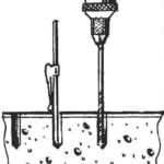 THE SIMPLEST DEPTH GAUGE
The pressure from the collet pencil, put on the shank of a suitable diameter drill bit, turning it into the simplest depth gauge required for control when performing nescopeck, equal to...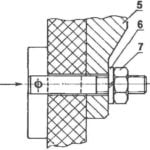 TRICKY BOLT
In carrying out various construction works it is often necessary to install and mount on wall panels are quite large and heavy products, devices and other structural elements. In...