Suspension. – independent, lever-torsion bar, telescopic hydraulic shock absorbers, double action. The wheels of the first and second driven axles (with steering gear gidrosistem).
For movement on the water an armored personnel carrier equipped with water jet mounted at the rear of the hull. Turn the APC on the water is the rudder control, interlocked with the steering control on land.
For self-recovery and pulling of similar machines jam, the armored front of the case there is a mechanical winch, driven from the drive shaft the right transfer case.
Means of communication the APC serves as a VHF radio station R-123. An armored personnel carrier is fitted with day and night observation devices. The hull is divided into three compartments: engine compartment, the fighting compartment and the driving compartment.
Legend:
SOME ASSEMBLY RECOMMENDATIONS
1. Frame
The framework consists of assemblies A; B;C;D;E;R;L (Fig. 1) Pattern of all parts frame
Glued onto cardboard with a thickness of 1mm, with the exception of the Assembly parts E and parts A13; A14, there is a cardboard with a thickness of 0.5 mm.
Assembly a (Fig. 2) items A1-A14) On the bottom of A1 to cut a hole to simulate suction bend to the intake, and then stick the parts A13; A14. In the aft part of the bottom to make deep incisions, to easily give the required radius when bending parts A1. Then install the longitudinal and transverse A2 AZ – A12 formers. Pay attention to the former A8, it is given by one detail with the Windows of the mines observation devices, where in these locations(Fig. 1 a) it is necessary to make deep incisions to the fold. For the convenience of Assembly at this stage, it is recommended to glue parts 55; 55.2; installation, A8, A8, then reinstall.
Assembly R; L. (Fig. 3) (items R1 – R9; L1-L9) This mirror Assembly, right and left, respectively. Look at the example of Assembly R (Fig.3). Gluing to produce on the order of part numbers. To details 1 alternately add details 2; 3; 4; 5; 6, further, to the finished design 7; 8 and connect them to each other detail 9.
Assembly; C; D (Fig.4;5;6) are presented in some details. For details B1 make deep incisions, to easily give the required radius when bent. Ready to assemble And glue the assemblies R and L, it follows that the design of the ARL. To the finished design to alternately glue parts C1; C2; B1; B2; VZ; B4: B5. Details for EOI pre-glue part (glazing inspection covers) 54; 54.1 M; 54.2; 54.3. On parts C1 and C2 (simulating lateral armor plates) projecting inside corner trim in the desired plane. Glue item D1 (Fig.6) pre-gluing the parts (shutters air flow units) 4; 4.1; 4.2; 4.3; 4.4; 4.5; (R;L). Frame for pasting a covering ready. If desired, the corners of the frame can be covered with strips of thin paper coated with color plating(available in the set).
Assembly E (alcove door actuator jet and sleeve reverse gear when the machine is afloat) (Fig.7) (items E1 – E6). Details first unit on cardboard to a thickness of 0.5 mm. On the details of the E6 and E1 in the same places, make deep incisions to the fold. To assemble the Assembly according to figure 7. To connect with the body only after full preparation of the body(laminated panelling) and pasting the actual Assembly E.
2.Case
Glue parts 1.5; 1.6; stick details 1.10(R,L); 1.11 (R, L); 1.12(R,L).Glue the bow part 1; 1.2; 1.4(R,L). Glue the parts aft 1.7; 1.1; Stick details 1.14(R,L); 1.15(R,L); 1.20(R,L). Glue parts 1.8; 1.9; Glue parts 1.16; 1.17; 1.18 between themselves and the finished design to be pasted in the frame. (IMPORTANT! The design should be parallel to the front of the upper hull(hatches commander and driver). Installed design to paste item 1.19 To ready and covered with body glue laminated covering niche door actuator jet with sleeves reverse. The case is completely ready.
3. Wheel
Item 28.1* pre-glued on cardboard thickness 0.5 mm. to Prepare, tformat and glue item 28 (for gluing the petals to use paper with a thickness of 0.1 mm office) (IMPORTANT! Sweep left and right wheels деталь28 on leaves this in pairs). Ready to paste item 28 item 28.1* Finished the right and left parts to glue together guided by the labels. Stick of the tread – деталь28.15 across the surface of the parts 18 being guided on labels. Paste collected items hub (see Assembly diagram).
4. Suspension
(IMPORTANT! Suspension parts are on the pages of this strictly by the numbering wheels) Part designation M made of wooden sticks (toothpick). Complete collection of pendants to make after all the suspension parts are ready. The build order indicated in the diagrams.
5. The flap balneotreatment
Details with the designation M made of solder or wire. Details 56.ZM and 58.4 M (frame plate) to glue on the already glued parts 56 and 56.2, and then to give the necessary shape of the whole flap. (IMPORTANT! If the model is planned for painting, the detail 56.1 stick on top of the part 56. Without painting detail 56.1 pasted between the parts 56 and 56.2
6. Tower
The details of the formers of the tower are glued on cardboard thickness 0.5 mm (detail 2** glued to cardboard with a thickness of 1 mm). (IMPORTANT! When gluing cylinder (part 2.6; 2.7*; 2.8 M; 2.9*) to pay attention to detail 2.9* podklyuchaetsya to item 2.6 at the junction that ensures accurate positioning of the machine guns when they are installed. After gluing the formers and install the cylinders to glue part2.13; 2.14; 2.15; when you cut the parts 2.17 it is recommended that you cut only the outer contour and inner holes to be cut after podleski details 2.16 KPVT Barrel can be made of different material (6 = 1.5 mm). Holes in parts 3.6 recommended after a preliminary twisting of the workpiece.
7. Manhole covers
Details of the manhole covers first unit on cardboard thickness 0.5 mm (option three layers of paper given layer of the sweep). In the manufacture of lids for manholes details 10.20; 10.21; only offered this option. (IMPORTANT! If you want to make manhole covers the opening note to the diagram, which shows how to do the cut workpiece.
TECHNICAL CHARACTERISTICS OF THE BTR -60
Combat weight, kg 10300
Weight without crew and troops, kg — 9300
The crew and troops, man — 10
Main sizes, mm:
length body — 7220
width of body — 2825
body height — 2055
the height of the arms (for tower) — 2420
base — 4240
Track, mm — 2370
Ground clearance (full load) mm:
when the tyre pressure is 2.5 kgf/cm2 — 475
when the tyre pressure 0.5 kgf/cm2 — 434
The angles of departure (at full load), grad.
front on vanooteghem— 42
rear body — 25
Minimum turning radius on the track
front outer wheel, m — 12
Speed, km/h:
maximum highway 80
maximum water — 9-10
Overcoming obstacles:
the greatest rise on solid ground, deg — 30
maximum angle of roll, deg — 25
ditch (width), m — 2
The reserve at movement on highway, km 500
The reserve afloat, h — 12.
The materials to build a model of the BTR – 60PB (download )
Recommend to read END-EXPRESS For more convenient use of masking tape or duct tape, there are special tapes with a knife, not giving to the same after use to stick the remaining end. In the absence of such a device... FROM SPANNER — RATCHET I propose to use a wrench as nidificantes in our time knob to operate the taps and plumbing expansions. This steel hexagon need to make an adapter with a square hole corresponding to the...
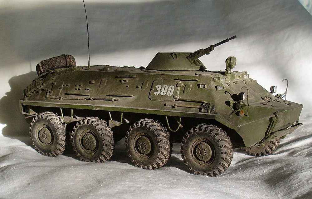 Scale model 1:25.
 The hull of the personnel carrier is closed, with a smooth bottom, sealed, made of armor plates, equipped with blower-separator to create a pressure cleaning charge air from radioactive dust and serves as a base on which are mounted all the units and mechanisms of the APC.