SOUND CONTROLLED MODELS

SOUND CONTROLS THE MODEL
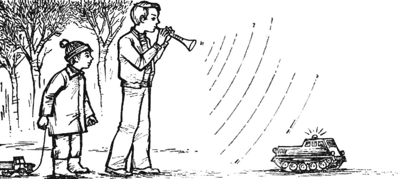
You obviously had to read about the models driven by sound signals. Receptor, which we offer to the reader reacts to an audio signal of a certain strength. The source may be, for example, a whistle, a whistle or sound a special transmitter commands. Equipped with this instrument model is performing in any sequence the commands: “forward”, “back”, “left”, “right”. The cessation of the audio signal or decrease it to a certain level is causing the stop model (stop). Here’s how the device works.

On models equipped with four alternately flashing lamps, each of them corresponds to a specific command. If the period of time during which lit one of the lamps, to the audible signal of sufficient strength, the model will execute the command. But as soon as the receiver stops “hearing” the sound, the model stops, and the command lamps will continue to flash alternately.
 
To control such a device requires certain skills. Therefore, the burning time of each lamp is first set equal to 2, and then gradually reduced, bringing it to 0.5 or even less.
 
The receiver is powered from two series-connected battery 3336L.
On the chip A1 (Fig. 1) is assembled a low-frequency amplifier, and the elements of D1.1 and D1.2 IC D1 — shaper of the reset pulse, which when you turn on the toggle switch S1 sets the pulse counter D2 in the initial state. On the elements D1.3, and D1.4 assembled clock generator, and on the elements of D3.1 — D3.4 chip D3 decoder. The pulse counter and the decoder are the distributor pulses. It has one input (pin 3 D2.2) and four outputs (pins 3, 6, 8, and 11 D3). The task of the allocator is to convert an input sequence of pulses to the output. The D4 chip is assembled, the Registrar of pulses. The role of electronic keys perform the transistors V1—V5. On semiconductor triode V8 is assembled by a voltage regulator.
 
Fig. 1. Schematic diagram of the sound receiver.
 
Fig. 1. Schematic diagram of the audio receiver.
 
Consider the operation of the device in the standby mode (ori the absence of a sound signal). Immediately after vkljucena S1 clock generator begins to produce pulses with a frequency of 1 Hz. First received on the input distributor pulse causes the output of the element D3.2 (pin 6) logic zero (logic level 0 corresponds to a voltage of 0.05 V, logic 1-3,6): the transistor V3 is opened and breaks the lamp H2. When PA input dispenser comes a second pulse opens the transistor V4 and the lamp H3. The third pulse will turn on the transistor V5, and with it the H4 bulb. The fourth pulse will open only the transistor V2 — lit lamp of H1. The fifth pulse again opens the transistor V3, as evidenced by the burning lamp H2. And so each lamp will continue to flash, and the model will remain motionless until it has not received a sound signal” let’s Say that it comes in between the ignition and extinction of the lamp bulb H1 (the forward command), the dynamic head B1 electrical oscillations through the transformer T1 and the capacitor C3 is fed to the input of the chip A1. Amplified its signal through a capacitor C6 comes PA recorder of pulses, and its output (pin 8 of element D4.4) a logical 0. Transistor V1 will be opened, and relay K1 will work. Contact plates K1.1, K1.2 break the supply circuit of the lamps N1 — N4 and turn off the oscillator. At the same time relay K2, during the burning of bulb H1, the transistor V2 is opened. His contact system K2.1 and K2.2 (Fig. 2) connect the motors M1, M2 to the power source: the model will move forward, as long as the audio signal. But once it becomes less than 3 mV, the output of the Registrar of pulses of a logical 1 transistor V1 is closed, relay K1 will turn off and the clock oscillator will continue its work. As a result, relay K2 and the motors M1, M2 takes out, and lamp N1 — N4 will be progressively erupt. Similarly, the model will execute the command “back”, if the sound signal will come in the period of burning lamp H3, the commands “left” or “right” — at the time of burning lamp H4 or H2, respectively.
 
To control model is not recommended for frequencies below 400 Hz because the noise of electric motors and gearboxes occupy a bandwidth of 25-350 Hz. The use of sound waves above 18 kHz limited frequency properties of the dynamic head.
 
In the sound receiver apply the following details. Dynamic head B1 0,25 GD-10 or any other resistance voice coil DC 6-10 Ohms. T1 — output transformer from a pocket radio “boy” or “Youth”. Core Ш3Х8 mm, the primary winding has 100 turns of wire PEV-1 to 0.2, the secondary 900 turns of PEV-1 0,1. Electrolytic condensers — K50-6, K50-3 or IT, and the rest of the KLS. Constant resistors — MLT-0,125 or ULM, R1 is the variable resistor GPA-1.
Д311А diodes can be replaced by Д311, KD503 with any alphabetic index; IC К155ЛАЗ (former designation К1ЛБ553) — PA К1ЛБЭ13, К1ЛБЗЗЗ; К155ТМ2 (former designation К1ТК552) — К1ТК332. Instead of transistors МП26А fit MP20— МП21, МП25—МП26 instead КТ315Г — KT315 with any alphabetic indexes. Static current transfer ratio of all semiconductor triodes — not less than 30. Relay: K2, K4 RES9 (passport RS4.524.202 or PC4.524.215), K1. K3, K5 RES-15 (passport RS4.591.003) with a trigger voltage of 6-7 V.
 
Lamp type ÌÍ2,5X0,15. Switch — П2К-1-1. The motor from the electrified toys or DIT-2. Spark quenching coils have inductance at 15 µg each. On the ferrite core 600НН length 12 and Ø 2.5 mm (from the inverter circuits of radio receivers “Selga”, “Falcon”) is wound with 25 turns of wire PEV-0,35 2,
 
To be sure and clear the operation of the switch, they need to be checked. For this purpose the winding of the test relay is connected to the voltage source 7 and a tester, measure the resistance between the closed plates. If it is zero, this relay is suitable to work. When the contact resistance is greater than zero, remove the protective cover and clean mating surfaces.
 
To the negative terminal of capacitor C3 connect the audio frequency generator with the output voltage of 3 mV, a frequency of 1000 Hz. At the time of setting the ULF desolder the negative terminal of the capacitor C6, connect a millivoltmeter, setting a limit of measurement 10 V. Selecting the value of resistor R3, until the millivoltmeter readings of 2.5— 3 V. Then the resistor R6 temporarily replace a variable with a nominal value 4.7 kω and connect the tester to terminal 8 D4.4. With the variable resistor set the arrow of the tester to the mark 0,03 — 0,1 V. the relay K1 should work.
 
If you now disable sound generator, K1 will return to its original state. at pin 8 of element D4.4 the voltage will increase to values of 1.8 — 3 V. Replace the variable resistor at a constant, set using R1 and the desired frequency of outbreaks lamp n check the operation of the entire device 8 whole.
 
Fig. 2. Electrical schematic chassis model.
 
Fig. 2. Electrical schematic chassis model.
 
Fig. 3. The arrangement of the elements of the receiver circuit Board ka.
 
Fig. 3. The location of the elements of the ka receiver circuit Board.
 
With lamps of the type МН1Х0.068 the resistance R7 — R10 increase to 47 Ohms.
 
The audio receiver is suitable for any moving models driven by electric motors. Lamp features on it at any place at the option of the designer, but so that they remained constantly in the field of view of the Modeler.
 
Dynamic head can be set over the motor with the diffuser facing upwards and cover with a plastic spherical cap, which is made of a 20-25 hole Ø 2,5—3 mm.
 
A. PROSKURIN, village of Golitsyno, Moscow region.

Recommend to read

  • THE WINNERS OF THE PILOT CLASSTHE WINNERS OF THE PILOT CLASS
    In the summer of 1981 in Moscow took place the traditional competition for experimental model airplanes. Today we introduce you to models — winners of these competitions. Student A....
  • HAMMER HOSESHAMMER HOSES
    She needed the breeder and the owner of the infield, with Nega will go faster the matter at harvest in the student's production of the brig!Oh and on home mini-farms. Yes and the...