
 Svobodnaya radio control model airplanes, gliders and helicopters is currently being implemented with the help of tiny transmitters that have levers or buttons to apply for the model of the desired commands. All of these devices have nothing to do with the controls of a real aircraft and need to develop specific skills and reactions. This means that the experience of control appears to be useless in the future, say, in the case of the transition has mastered them to the training flights in a glider, and especially on the plane.
By itself the question arises: is it right? Isn’t it better to make the controls of the transmitter is similar to aircraft by not only their appearance, but also by key (and thus generated) steering reactions? After all, if today some “inventor” offered to change the design and operation of aircraft control, making it identical to the existing management radiomodule, it is, to put it mildly, would have raised a laugh. So why is the latter not improved and is not close to conventional systems? Maybe it is more convenient?
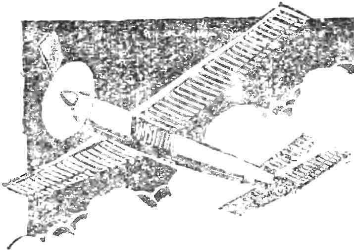
Not at all, — in one voice said the radio operators who have tried developed by E. Henry (USA) new remote control flying radiomodule. This remote is a simplified and lightweight the pilot’s seat, mounted on a portable base that can be rotated 360° around the vertical axis for continuous monitoring model to fly. Seat linked with the controls of the aircraft type: knob, pedals, Gaza strip, connected by rods and cables with the command radio transmitter located in front of the pilot (Fig. 1).
“To control a flying model of this remote control to only easy, but also pleasant: experience this kind of feeling, as if he were in the cockpit of this model — so said about the new unit-known aerobatic pilot Jim house. — Move the handle forward, and the sky opens its arms to you. Gaining height, lay in a course. Model easy to manage and responsive to your every command. The stick and the model follows several loops. Half roll, turn on the slide and other aerobatics are obtained pure and graceful”.
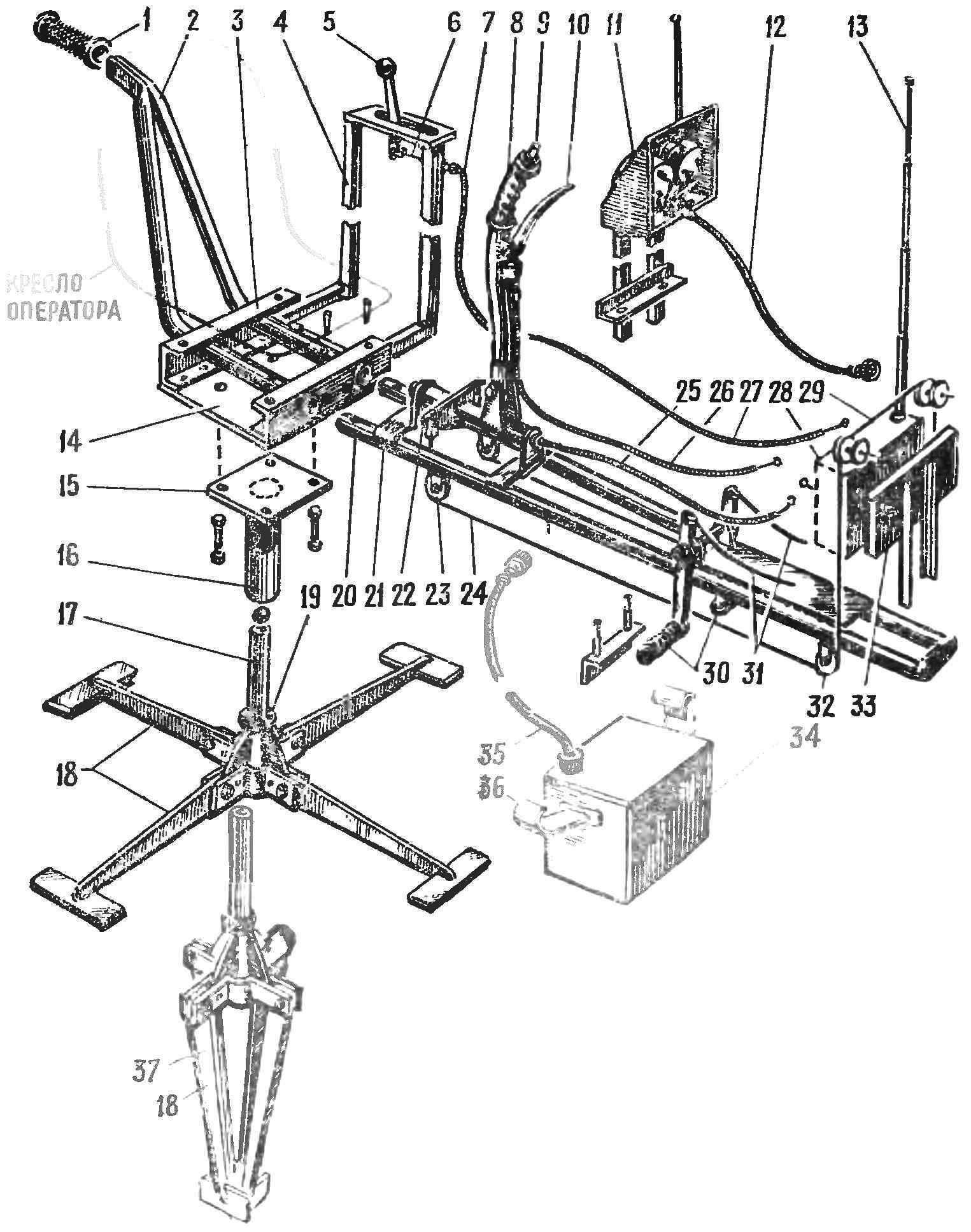
Fig. 1. The overall layout of the chairs with a predominant use of metal parts:
1 — the rubber handle of the rotary lever, 2 — pipe, a pivoted lever, 3 — channel base driver’s seat, 4 — subframe of the Gaza strip, 5 — arm Gaza, 6 — throttle rod (the open part), 7 — throttle rod (flexible sheath), 8 — stick control Aileron and Elevator, 9 — button off engine, 10 — lever brake control chassis, 11 — instrument cluster, 12 — patch cable instrument cluster, 13 — antenna of the command radio transmitter 14 — the bottom of the box base the seats, 15 — flange rotary tumbler, 16 — rotary tumbler, 17 — front rotary tumbler, 18 — folding legs Stoics, 19 — thrust ball bearing rotary tumbler, 20 — fangs of the frame control, connecting it with the box, 21 — bridge mounting of the steering shaft and handle, 22 — duplica rocking control ailerons, 23 — roller control cable Aileron, 24 — control cable Aileron (open and closed circuit), 25 — rope of Elevator control (flexible sheath), 26 — control cable brake chassis (flexible sheath), 27 — throttle rod (flexible sheath), 28 — command transmitter, a 29 — control cable Aileron, 30 — pedals control rudder, 31 — control cables, rudder (chain can be closed and unclosed), 32 — roller control cable Aileron, 33 — front command of the radio transmitter 34 — box with external power supply system, which serves at the same time for balancing, 35 — patch cord, 36 — hook for suspension to the tubes of the frame control, 37 — stand with legs folded for transport.

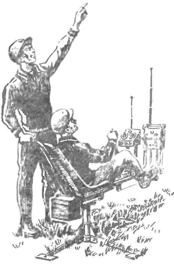
Fig. 2. Overall layout of the chair.
The panel essentially is a simplified simulator. It can be used with success not only in modeling but also in the flying clubs, flight schools, flight departments, as well as a useful and entertaining attraction — of course, with some structural modifications. Therefore, we begin the publication of drawings of the original simulator, prepared for our magazine L. P. Vasilevsky.
As can be seen from the drawings, the exerciser is simple in construction and can be built from scrap materials in any model circle. Depending on what the radios have model airplanes, need to Refine or modify nodes control the command station. But it also is not the challenge in and of itself very interesting.
The controller Svobodnaya models in the working position shown in figure 1. His diagram in figure 2. Operator-“pilot” sitting in a chair and controls the model using the handles, pedals and the Gaza strip is absolutely the same as on the real aircraft. Behind the assistant, watching the model: depending on the flight conditions he turns the chair so that the pilot is all the time good saw the model, and, if you give him the necessary advice.
As you manipulate the model on the ground (taxiing to the start, etc.) pilot operated pedals and the Gaza strip, and during takeoff, flight and landing — and also handle. The proportional control. It incorporates coil springs, simulating aerodynamic loading on the rudder and returns a handle and pedals in neutral position. There are also trimmers available during the flight control model On the dashboard mounted indicator of the field strength of the transmitter and the time relay, operating in the range of 0-15 min.
The remote for transport can be easily and quickly disassembled into three nodes and whose total weight does not exceed 60 kg.
All work to manufacture a panel divided into two stages-the manufacture of the base, which includes a support, a seat carrying beam and the attachment of a radio transmitter, and installation of the entire system of control pedals of the rudder handle rudder and ailerons, the Gaza strip, trimming of Aileron and Elevator, control panel wiring.
For the base you will need strip and sheet steel, although acceptable using alloy materials. Design and basic dimensions of the folding legs is shown in the figure and a special explanation is not required. During disassembly of the unit support feet are folded like the spokes of an umbrella, and the entire device occupies very little space.
On the vertical rack support fits over cut pipe Ø 50-60 mm, to which are attached the platform of the seat and the horizontal beam that carries all the rest of the equipment: handle, pedal, radio, dashboard. To provide easy rotation of the whole system, plug the lower end of the pipe installed angular contact bearing No. 36206, and at the top end — more light bearing No. 206. Square metal plate attached to the upper end of the pipe, can be installed on the bolts or is welded. It, in turn, bolts to the frame base chair with armrest and handle for a helper. The chair itself, it is advisable to get ready — now there are many easy and convenient designs in furniture range; suitable seat such as the micro-car, only cards: laminated of fiberglass. The main thing — to adjust it to sit conveniently and knees of the pilot does not rise too high. The optimum proportions shown in the diagram (sizes for a person of average height).
If the finished chair is not found, the following is a sketch of the seat, which can be made their own from scrap materials.
Regardless of how to run a beam in the first stage of work includes the installation of the transmitter (or related instrument) that much easier in the second phase, connecting to it and pull the cables from the controls. The drawings given us mounting units consistent with the units of radio equipment “Suprone” of domestic production.
Installing the transmitter ends the first phase of the work. In the third issue we will tell you about the mechanical installation of the control, the adjustment unit prior to flight, will give some recommendations on pilot technique.
Crafting key components of the simulator, you can begin to assemble the control mechanism transmitter. As already mentioned, gives good results with only the use of proportional radio equipment, for example, domestic kit “Suponer”. Install discrete equipment pointless, since the management and the real plane have nothing in common.
The layout of the controls is proportional to the radio type installed on the “chair”:
A variant with predominant use of fittings and return springs: 1 — vertical yoke, 2 — wire control vertical rocker 3 — return spring 4 — strut mount return spring, 5 — pin antenna, 6 —recoil horizontal yoke 7 roller control cable vertical slide, 8 — axis of rotation horizontal yoke 9 — focus fitting of the control cable horizontal curtain, 10 — nozzle, 11 — a cable in a flexible sheath, 12 — wiring to an external power source.
B — variant with the use of the outdoor cables: 1 — outdoor control cable horizontal yoke, 2 — top roller, 3 — choke control cable vertical yoke, 4 — strut mount fitting, 5 — control cable vertical slide, 6 — ball bearing vertical wings, 7 — return spring, 8 — strut mounting return springs, 9 — whip antenna, 10 — the mount of the upper roller, 11 — the spring open cable management horizontal curtain, 12 — adjusting strap, 13 — finger control of the horizontal yoke 14 — bottom roller, 15 — control cable vertical yoke (flexible sheath), 16 — wiring to the instrument panel, 17 — horizontal arm 18 is a vertical arm 19 — wiring to external power source 20 — hour fitting of the control cable slide switch (flaps, brakes and so forth an unambiguous command), 21 — head slide switch, 22 — sealing of cable terminal and the installation of the fitting.
Used equipment needs to be adjusted on the following eight teams: left and right; up and down; roll right — roll left, big turns, small turns of the engine. Team right and to the left is transmitted by the movement of foot pedals, the team’s up-and-down and roll — handle engine control with the Gaza strip. Communication with the transmitter is mechanical, rigid rods and cables, as shown in No. 1. An indispensable condition for the smooth operation of the mechanism is the absence of backlash and jamming; the most crucial part — the scenes directly related to the control levers on the front panel of the transmitter. The kinematics of the transmission of commands from right to left is relatively simple, which is not, unfortunately, say about the wings, transmission, four teams (up-down and roll). The fact that to perform a coordinated maneuver in the air (like a deep bend, the half roll barrel) is required at the same time and strictly measured, dieeeee handle from itself, to itself and to the sides. A good pilot performs these movements unconsciously, physically feeling the response of the aircraft and respectively scaling the amplitude of their movements. We do not have a physical connection with the model I. control her behavior, only visually. Enough for a few seconds to lose the model from the view, and pattern flying is hopelessly flawed. The same thing can happen if the mechanical part of the control wiring is incorrect or late transfer to the Executive part of the transmitter pen movement.
The experiments showed that noisy with longitudinal slots is best made of brass or bronze, this will reduce the friction on the steel rod lever on the transmitter. The inside edges of the slits and the surface of the planks should be treated with sandpaper and polished on a felt circle with GOI paste; this treatment eliminates the possibility of jamming of the mechanism in a complex (two-digit) movements of the control stick. Swivel the control system must be accurate enough that all the parts move without excessive effort and at the same time did not loose in Operation. All the joints of the control system it is desirable to make ball bearing, in a pinch you can use brass or bronze bushings with steel fingers, picking them to each other with a tolerance that provides for the free movement without backlash.
Before first flight you should be very careful to check and adjust the operation of the control system, transmitter and receiver on the model as well as the serviceability and correct operation of all servos. The model should be set at different distances and at different angles relative to the transmitter.
L. WASILEWSKI
Recommend to read
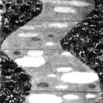 CONCRETE PATTERNS ON THE TRACKS
Beautiful and elegant look of Park paths, lined with small plates. Why not adopt a similar method of covering tracks in the garden area? Because concrete is more durable and clearly...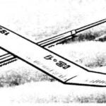 “SCHEMATICA” CLASS B1
Proponents of class rezinomotornaya expense of building a traditional model B1, do not turn the page of the magazine, seeing the drawings of equipment, by the external signs relating to...
