
 The su-7, were armed with Soviet air force, is a typical representative of tactical aircraft of its time. Being built at the beginning of the cold war as a fighter, he turned into a fighter-bomber and a carrier of nuclear weapons. Su-7 is constantly improving his combat capabilities were expanded and the flight characteristics were improved, which allowed the aircraft to become rather successful commercial project and long enough to stay in service in many countries. Its rugged and reliable design became the basis for the development of many interesting projects, one of which was the aircraft with variable sweep-wing su-17.
DEVELOPMENT
The history of the su-7 began with the late 1940’s-early 1950-ies, when the Soviet Union began to develop requirements for a new fighter with high supersonic speed and with more practical ceiling that could intercept a high-altitude reconnaissance aircraft and confront the prospective enemy fighters.
According to experts of military aircraft, it was required two new machines: a front-line fighter with the possibility of strikes against ground targets, and clean the interceptor. New frontline fighter maximum flight speed was to reach 1800 km/h, the ceiling of 19 000 m. For the interceptors desired speed is increased by 100 — 150 km/h and a service ceiling of 1000 m. the Range of both machines at high altitude without external fuel tanks was equal to 1400 km Armament tactical fighter was to consist of three 30-mm guns, and interceptor, two guns of the same caliber. The interceptor was planned to equip the radar.
Of fighter KB for this kind of work could take only firms of Mikoyan and Yakovlev, who regularly received funding, built a production aircraft and was engaged in the R & d work, but the Lavochkin design Bureau is almost completely shifted to rocket theme. Almost immediately after Stalin’s death, his successor Malenkov reinforced fighter direction, returning into operation of the disgraced designer Pavel Osipovich Sukhoi. Design Bureau, a non-partisan, Pavel Osipovich was closed in 1949 due to his conflict with Minister of the armed forces of the USSR. A. Bulganin. Although according to the official version, Sukhoi has closed due to a disaster experienced interceptor su-15 and the General “inefficiency” of the work.
In may 1953 at OKB-1 under the leadership of Sukhoi began work on two projects. Both aircraft were considered in two variants, differing in the shape of the wing in the plan. One wing had a traditional arrow-shaped, and the other new for that time – triangular. A front-line fighter with swept wings were designated C-1 and triangle – T-1. Respectively called interceptors, p – 3 and T-3.
To achieve C-1/C-3 high-speed aircraft Pavel Osipovich set the wing sweep of 60°, the line of the 1/4 chord, and use the new turbojet engine (TRD) designer Arkhip Mikhailovich Lyulka AL-7F, with the stated thrust in afterburner 10 000 kgs. However, the engine was not yet ready, and as a temporary measure for prototypes could deliver his accelerated option AP-7, with a third less thrust. Despite this, calculations show that even with such a weak turbojet aircraft “C” will be released at supersonic speed.
In favor of Dry played the tactical aviation of the USSR the situation. Commanders and pilots of combatant regiments feel confident enough, unlike the pilots of air defense, which could not cope with the increasing flow of air violators. Tactical fighters probable opponent the beginning of 1950-ies was not much record performance, and on the battlefield MiG-17 was perfectly solved your task. His main opponent was an American transonic F-84F Thunderstreak. The aircraft was armed with six heavy machine guns and could carry external sling one nuclear and four conventional bombs caliber 450 kg the Wing sweep of 40° and the engine thrust 3270 kgf provided the “American” maximum airspeed without external suspension 1160 km/h At its manoeuvring characteristics and small arms, he lost the MiG-17. For example, the rate of climb at the altitude of 6000 m at the Moment was 27.5 m/s, and the F-84F -26 m/s; the radius of the bend at the MiG-a – 410 m, and the F-84F – 630 M.
The French mass-produced its tactical fighter Mister IVA, which was slightly better F-84F, but he could not boast of superiority over the 17-m Instantly.
Best of all on the General background looked British tactical fighter Hunter. Its rate of climb at the altitude of 6000 m was almost 30 m/s, and the radius of the bend near the earth were close to the radius of the MiG. In addition, respect for the cause and his four 30-mm guns, as well as the fact that the “Hunter” in 1953, managed to set a world speed record on the basis of 3 km 1171 km/h.
As for the stormtroopers, of such specialized aircraft in the US air force and NATO did not exist. For attacks on ground targets in the interests of the land forces is out of date piston fighters P-51 Mustang, F4U Corsair and jet fighters F-80, F-84 and F-86. Their toughness, bomb load, range and accuracy of the use of weapons against ground targets left much to be desired. A real attack aircraft A-1 Skyraider was the only carrier-based aircraft, but it’s on the vast expanses of the Soviet Union “did not make the weather”.
This situation bothered the Western military and in February 1952 at the 9th session of the Atlantic Council in Lisbon took the decision to develop a light fighter-bomber, which was to become the standard aircraft for the member countries of NATO. Declared requirements for such aircraft and the course of the competition, which culminated in the adoption of the G. 91 aircraft, of particular concern in the Soviet Union did not cause.
But the situation on the “front” of the cold war at the time changed very quickly. Since the spring of 1953, the air has risen supersonic tactical fighter jets: American F-100, F-101 and French Super Mister. Against them OKB Mikoyan offered the new front-line fighter MiG-19. The test aircraft has just begun, but experts it is clear that their performance will be close and will not provide a decisive advantage in a dogfight. Hence arose the desire of all “players” in the field of extermination in the Soviet Union to build an even better aircraft. And to do it fast progress in the field of engine and aerodynamics have opened before the designers the ability to overclock the machine up to two times the speed of sound.
Fighter “s” and “T” Sukhoi came in very useful.
They just worked ahead of the curve. Therefore, the proposal of Dry received the approval and support of the government. The corresponding decree was released on 8 August 1953. To take the first high-speed machine to the test required no later than may 1955.
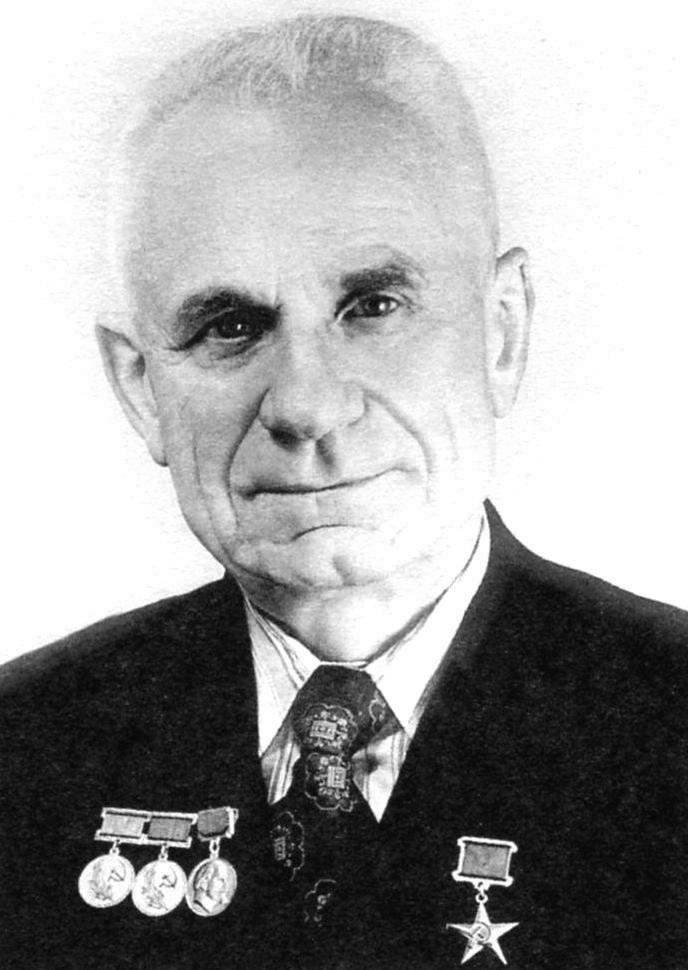
Designer P. O. Sukhoi
Similar projects have advanced and the main competitor of design Bureau No. 155 Mikoyan and Gurevich. The team is the most powerful fighter of the Bureau of the country also began work on a front-line fighter with swept and Delta wing. Options received the designation E-1 and E-5, respectively. As Dry, Mikoyan Gurevich wanted to determine the best aircraft in the comparative trials. As the power plant of “E” was planned to use turbojet engines Mikulin AM-11 with a thrust in afterburner 5100 kgs.
The deadline set designers s-1, was hard, but the design was quite brisk, because the design of C-1 was based on a previous draft of Dry, known as “P” (the first su-17) was built, but never flown. For the team of OKB-1 also is not in vain and his previous work. Before the arrival of the Dry engineers, the Bureau has provided a copy of the F-86 Sabre. The most successful American technical solutions “went smoothly” with “Sabre” on s-1. Was taken: suspension flaps, irreversible boosters and some elements of the hydraulic system. The hydraulic pressure is also consistent with the pressure in the system, the F-86 – 210 kg/m2. This value slightly increases the thickness of the piping, but seriously reduced the dimensions of the actuators and improve their performance.
Draft project-1 completed in the fall of 1953. Working drawings of aircraft Sukhoi demanded to be completed by December 31. The design Bureau had to move in the design, near Kuhlmann put beds and food brought directly to your workplace. Thanks to the work completed in time.
In early 1954, Sukhoi has allocated a pilot plant for the construction of the first instances of a fighter. OKB-1 was renamed according to the number of the plant at OKB-51. Now Dry had everything we needed. Clarification of drawings and placement of equipment in the plane was produced with wooden layout, which passed the Board of the customer. She adopted the outward appearance of the car in February 1954.
The summer has started building two prototype s-1. The first was intended for flight testing and one for static. The static instance done faster and began to load to check the strength of the structure.
At a load of 85% of the estimated something unexpected happened – broke down the rear wall of the wing. The destruction happened near the junction with the main beam, which is sometimes referred to as “strut”. A weak spot had to reinforce with steel plates and make the appropriate changes in the design of flight instance. The following loading failure occurred under load of 101%. Dry believed this figure to normal weight perfection structures, and further strengthening was not carried out.
Originally came with aerodynamic baffles on the wing, which increases the resistance, preventing the flow of a stream, but with loads of cracked. To give flexibility, the septum was cut into several separate sections. The rest of statisticaly confirmed the calculated data and s-1 with a time-accelerated engine AP-7 began to prepare for flight.
Powerplant-1 was not quite normal, so we have to consider it in more detail.
In developing its new turbojet engine AL-7, Arkhip Mikhailovich Lyulka decided to increase the thrust by increasing the degree of air compression in the compressor. This problem could be solved simply by adding stages, but it increased the mass and size of the engine. And it was possible to apply the so-called supersonic compressor. In it, thanks to a special profile of the blades, the air flow between them moves faster than the speed of sound. Stages has less pressure but more air. Accordingly, less weight and more traction.
However, the supersonic compressor is very difficult to achieve stable operation. In addition, the blades are subjected to extreme loads and even small nicks on the surface can lead to their destruction. In view of these shortcomings, usually supersonic’t do all the steps, but only a few, then make them work easier.
Cradle decided to make a supersonic only a first step. By its efficiency it replaced 3-4 subsonic.
To improve upornosti wheel diameter new level was increased, and the diameter of the old stages remain the same, because of this air tract characteristic hump. During the tests, the engine starts to work and showed the design characteristics, but the hump did not give rest to the team of designers. However, all their attempts to rectify the “ugliness” did not succeed. Smooth compressor stubbornly did not want to work. In the end, he was left alone, and the unusual shape of the flow part of the compressor of the AL-7 was, as they say, his “calling card”.
Cradle even joked about it. Once his design called for the American delegation from General Electric. Leading specialist firms seeing compressor “Seven”, inquired the Cradle: “Why does Your engine compressor hunchback?” To which he jokingly replied: “He was born like this!”
Supersonic tier raised the compression ratio of the compressor at AL-7 to 9.1. While the previous AL-5, with the conventional compressor, it was only 4.5. Max pull compared to the Five increased to 1340 kgs.

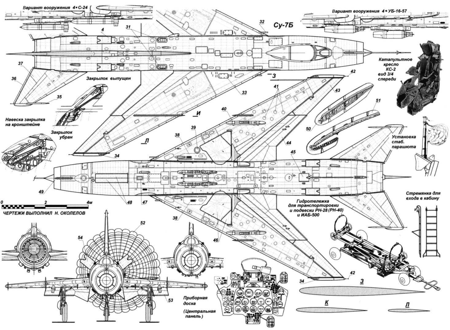
The su-7B:
1 – rudder, 2 – node hinge of the rudder; 3 – operational access doors; 4 – brake; 5 – the movable part of the lamp; 6 – canopy canopy; 7 – antisurge fold; 8 – reinforcing panel; 9 – fuselage pylon; 10 – wing pylon; 11 – lock braking parachute; 12 – LDPE-5; 13 – DUAS-133-8; 14 – the chair of COP-2; 15 – movable part of the lamp in open position; 16 – AMZ-53МС in the working position; 17 – gazovoy rope; 18 – thrust pads; 19 – PTB-600; 20 – wheel nose gear; 21 – nose strut; 22 – a ladder; 23 – fold the nose landing gear; 24 – safety Gazovaya mesh; 25 – fairing electricity and radioprofi; 26 – aerodynamic bulkhead No. 1; 27 – aerodynamic bulkhead No. 2; 28 – wheel main landing gear; 29 – gidrotehnika; 30 – nozzle system jet protection; 31 – louvered air vent with tape bypass; 32 – gun; 33 – Luke equipment ammunition; 34 – ANO; 35 – anti-flatter load; 36 – plate trimmer of the Elevator; 37 – the steering wheel height; 38 – Luke cannon Bay; 39 – off and landing (taxiing) headlight; 40 – wing pylon; 41 maintenance hatches; 42 – static electricity discharger; 43 – Aileron; 44 – flaps; 45 – drag chute container; a 46 – fold main landing gear; 47 – shutter; 48 – fold the nose landing gear in the closed position; 49 – antenna SOD-57; 50 – aerodynamic bulkhead No. 2; 51 – aerodynamic bulkhead No. 1; 52 – brake parachute in the released position; 53 – flaps in the released position; 54 – brake in the released position
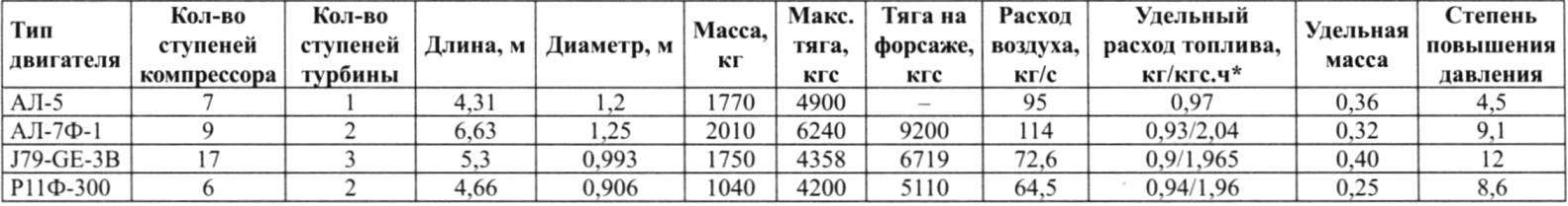
Engine-competitor AM-11 (Р11Ф-300), designed for aircraft Mikoyan OKB Mikulin had fully supersonic six-stage compressor.
But General Electric went simple by increasing the number of stages. Its designers are “piled” them into J79 as many as 17 pieces, but brought the compression ratio to record-breaking 12!
Very different ways went to the designers and to ensure the sustainability of the operation of the engine, and in the fight against surging.
Cradle has applied the by-pass air from the flowpath. The “extra” air is given by the fourth and fifth steps, and was released into the atmosphere through the holes in the engine block that was aligned with the two cutouts in the upper part of the fuselage of the aircraft. In normal condition, the holes on the engine were closed by steel bands. Bypass is the most simple and at the same time, the most uneconomical system. At the time of opening of holes in the housing turbojet engine at reduced thrust and increased fuel consumption.
From General Electric to support the work of the engine used rotary guide vanes of the compressor. This system has virtually no “side effects”, but it is much harder and more expensive bypass.
The engine Mikulin was applied two-stage compressor, which is nothing at all requires all the regulation provides the rotation of the rotors of low and high pressure with different speeds.
Comparing the engines together, you need to know that more perfect TRD is the one from which the given customer pull is achieved at minimum mass and costs of the fuel and air. With every extra kilogram of engine weight increases the aircraft weight by roughly three kilograms.
Constructive level of perfection of the engine can be identified by its specific gravity – the ratio of the mass to maximum thrust. The smaller, the better – the more rationally chosen its constructive scheme.
As can be seen from the analysis table, the best of the three turbojet engines can rightly be called the engine AM-11 (Р11Ф-300) Alexander Alexandrovich Mikulin. But to bring its best product Mikulin did not have time. In early 1955 it was removed from the post of chief designer with a mocking phrase in order: “Tov. Mikulin makes mistakes … confusing and difficult to work to create engines”. So that’s something. The reason for this turn of fate was the friendship of Alexander Alexandrovich with the Chairman of the Council of Ministers Malenkov. It it often “used” and made himself a dangerous enemy in the person of the Minister of aviation industry Dementieva and chief designer of Klimov. They dealt with Mikulin immediately after Khrushchev was removed Malenkov. Choosing a moment when Mikulin was not at work, Dementiev and Klimov came in his design, a quick read written in haste order and put a new head – S. K. Tumansky, a friend Dementieva. Now these things are called “raider seizure”. So AM-11 to serial production brought already Tumansky, he changed the designation of TRD AM-11 R11, deleting from history the name of his talented predecessor.
Designer Am Cradle
Lulkowski engines AL-7 was not the best in its class, but their desire had no equal. And focusing on traction, Dry, in General, was not mistaken. However, to place a fairly large engine, its systems, and fuel was only sufficient volume in the fuselage. Respectively, and s-1 from the competition looked very impressive.
16 July 1955-1 brought to LII airfield in Zhukovsky. A test of a new car designated the pilot of the Lavochkin design Bureau Andrei G. Kochetkov, “their” pilots of the Sukhoi design Bureau had not yet. After 11 days Kochetkov made on the s-1 first taxiing. Then followed by speed runs. Everything went quite smoothly, the plane unpleasant “surprises” is presented.
7 September was scheduled for the next high-speed run with the approach, the release of the brake parachute and a stop at the end of the strip. Subsequent events Kochetkov in his memoirs, describes: “we Decided to spend the approaching night, when the airport is empty. The flights stopped, I pulled up at the start. Gave full engine speed, dispersed the aircraft to the speed of separation, he tore off a plane from the strip. And suddenly something unexpected happened. The plane is a small gap rose to a height of not less than 15 meters. I immediately removed the momentum, but soon found that strips for planting is not enough and the plane will be broken…Increased speed to maximum and began to climb”.

TURBOJET ENGINES AL-5
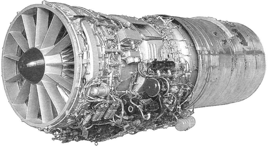
TURBOJET ENGINES AL-7Ф1
Gaining altitude 50 meters, Kochetkov made a standard fly in a circle and successfully landed the plane. His first impressions after the flight was positive. As a disadvantage, the pilot noted only a small pitching, which arose immediately after the separation because of the small effort at the control handle and disappeared after retracting the flaps and turn on the loading mechanism.
Dry and the Cradle were very satisfied. The OKB held a solemn meeting at which happy Dry congratulated those who built the machine.
Until January 1956-1 made 12 flights. After that, the machine I installed the regular AL-7F engine with afterburner. Is Kochetkova over the plane with a new power plant and further work led by test pilot Vladimir N. Mahalin. During the tests Mahalino failed to accelerate on the C-1 and M=2,03 (2170 km/h). High-speed requirements of the customer were exceeded, but the range left something to be desired. High specific fuel consumption AL-7F was not possible to achieve half of the desired 1400 km Dry decided to increase the amount of fuel on the second prototype S-2.
DESCRIPTION OF THE DESIGN OF THE SU-7B
The su-7B is an all-metal, cantilever signalen with swept wing (sweep 60° on the line of 25% chord), with swept tail surfaces and controllable stabilizer, performing the functions of the Elevator.
Fuselage – all-metal semi-monocoque circular cross-section. Power set consists of 43 frames, 7 spars and stringers 23. The middle part has a diameter of 1550 mm. From the frame No. 15 to the inlet cross-section gradually decreases and the line of its centers is omitted. The maximum diameter of the rear – 1634 mm. the Line of centres of sections of the tail up towards rear sections of the fuselage.
In the fuselage are: a pressurized cockpit, an engine, a considerable portion of fuel and equipment.
The air intake is at the front of the fuselage. To reduce losses at the entrance and ensure stable operation of the engine on the axis of the air intake at the front set movable cone and antisurge sash.
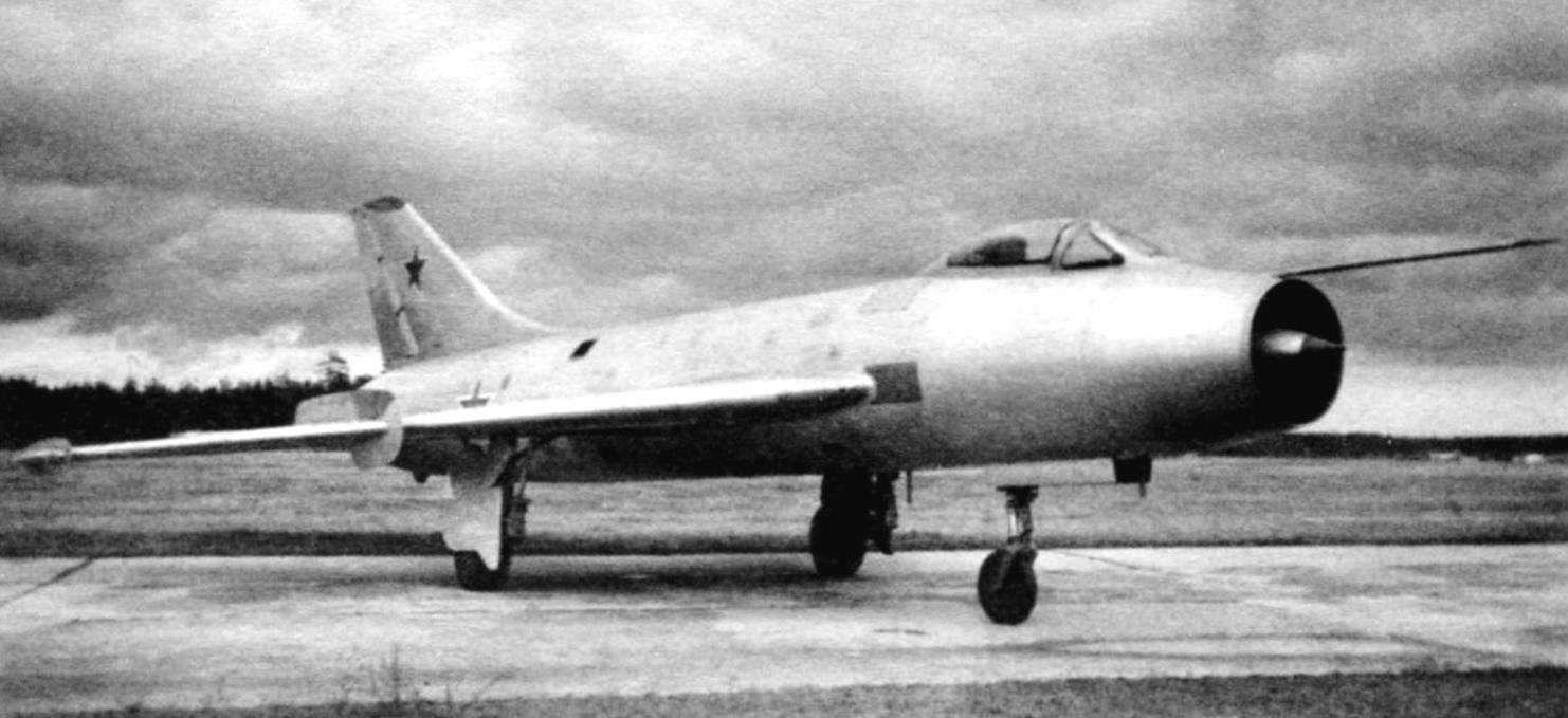
Experienced fighter s-1 (Sukhoi photo)
Cone and shutters are controlled automatically by electro-hydraulic system. Front of cabin, the air channel divides into two branches oval in cross-section, passing around the sides and the back connecting it to one channel of circular cross-section.
To the fuselage mounted wing, and keel with rudder, half of the stabilizer and front landing gear. In the lower part of the fuselage is installed the attachment points of the beams, which can accommodate discharged fuel tanks or weapons. In the rear fuselage are four brake flap area of 0.33 m2 each, the container landing braking parachute and tail wheel. The maximum angle of deflection flaps – 50°. Tail wheel serves for protection against damage to the rear fuselage in the event of a landing with an angle, a large normal landing. The support includes a lock for attaching the rope brake landing parachute. At the bottom of the anvil has a groove for the cable.
The main materials used in the construction of the fuselage, – the aluminum alloys D16 and V95. A number of important power units are made of steel 30ХГСНА.
In the area of exit of the barrel of a gun from the sock of the wing to the fuselage skin riveted cover plate made of heat-resistant steel.
The cockpit sealed ventilation type. The air for working the air-conditioning system is taken from the 5th or the 7th stages of the compressor of the engine.
In the cockpit set ejection seat, pilot, COP-4. It provides a safe ejection in flight, and on takeoff and run at speeds of over 140 km/h.
Wing aircraft with a sweep angle of 60° of the line of 25% chord. Wing setting angle is +1°, the shear V is -3°. The wing consists of two detachable consoles have in terms of trapezoidal form. Each console installed: the Aileron with the weight and aerodynamic compensation, retractable flaps, and two aerodynamic partitions.
Table comparative characteristics of the turbojet engine of the aircraft su-7, F-104A MiG-21F
Power set of the wing consists of longitudinal and transverse. In the longitudinal set includes: a longitudinal main beam, the rear wall, a small beam and stringers. Cross set consists of 30 ribs and one extra sock. The structural elements of the wing consists of the following compartments: socks, weapons bays, the compartment of the main landing gear, a pressurized fuel compartment fuel container and the tail part. The upper casing of the chassis to increase rigidity supported by the inside of a profiled sheet of aluminum.
Weapons bays located in front of the root portion of each console. In front of the right console, in the area of the first aerodynamic partitions, installed film camera CCA-5-750С.
In the middle part of each console between the spar and the rear wall, the ribs 12 and 22 is hermetically sealed fuel compartment with filling hole and drain device. The upper and lower surfaces of the fuel compartment is formed by a monolithic panels.
The ailerons have the weight and aerodynamic compensation, suspended on the wing at three points. Deflection angles of Aileron ±22°, the axis of rotation is located above the plane of the chords.
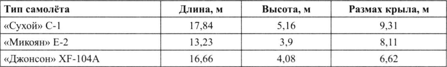
Table of comparative size of the fighters
Retractable slotted flaps located in the rear part of the wing, between the sides of the fuselage and the ailerons. Are issued and retracted the flaps by means of two hydraulic actuators on rails located on the ribs 12 and 19 the rear wing. When you release the flaps deflected at 25° down.
The tailplane is swept, consists of the horizontal tail -of the stabilizer and the vertical stabilizer – forces and keel with rudder. The sweep angle of the horizontal and vertical tail along the line of 25% chord equal to 55°.
The stabilizer is set at 110 mm below the horizontal construction of the fuselage with the mounting angle – 1°. The stabilizer consists of two halves, each of which is articulated on ball bearings and rotates relative to the axle, set at an angle of 41°30′ to the longitudinal axis of the aircraft. Each half of the stabilizer is operated by a booster.
The vertical tail of the aircraft is of conventional type. The keel is mounted on the fuselage to the frames No. 38 and No. 43. The rudder, controlled by a booster has a weight balance. In Kiel hosted Radiotechnika antenna and connected the radio; to ensure their work is top of the keel and rudder are made of radio – transparent material- fiberglass.
The design of the empennage is all-metal, riveted with running covering.
Landing gear – tricycle consists of two main struts, located under the detachable parts of the wing, and a-pillar mounted under the nose of the fuselage. The main racks are cleaned traffic to the longitudinal axis of the aircraft in a niche of the root portions of the wings, and the front is removed by forward movement, in a niche under the floor of the cockpit.
On the main racks mounted brake wheel high pressure brand CT-69 (880X230) with disc brakes on the front – wheel non-braking high pressure brand К283 (570X140). Amortization – oil-pneumatic. Track chassis -3830 mm, base (with neobiotic shock absorbers) – 4920 mm.
Landing braking parachute PT-7, which are used to reduce the mileage of the aircraft after landing placed in the container installed in the rear fuselage. Release management and discharge chute, electric, remote.
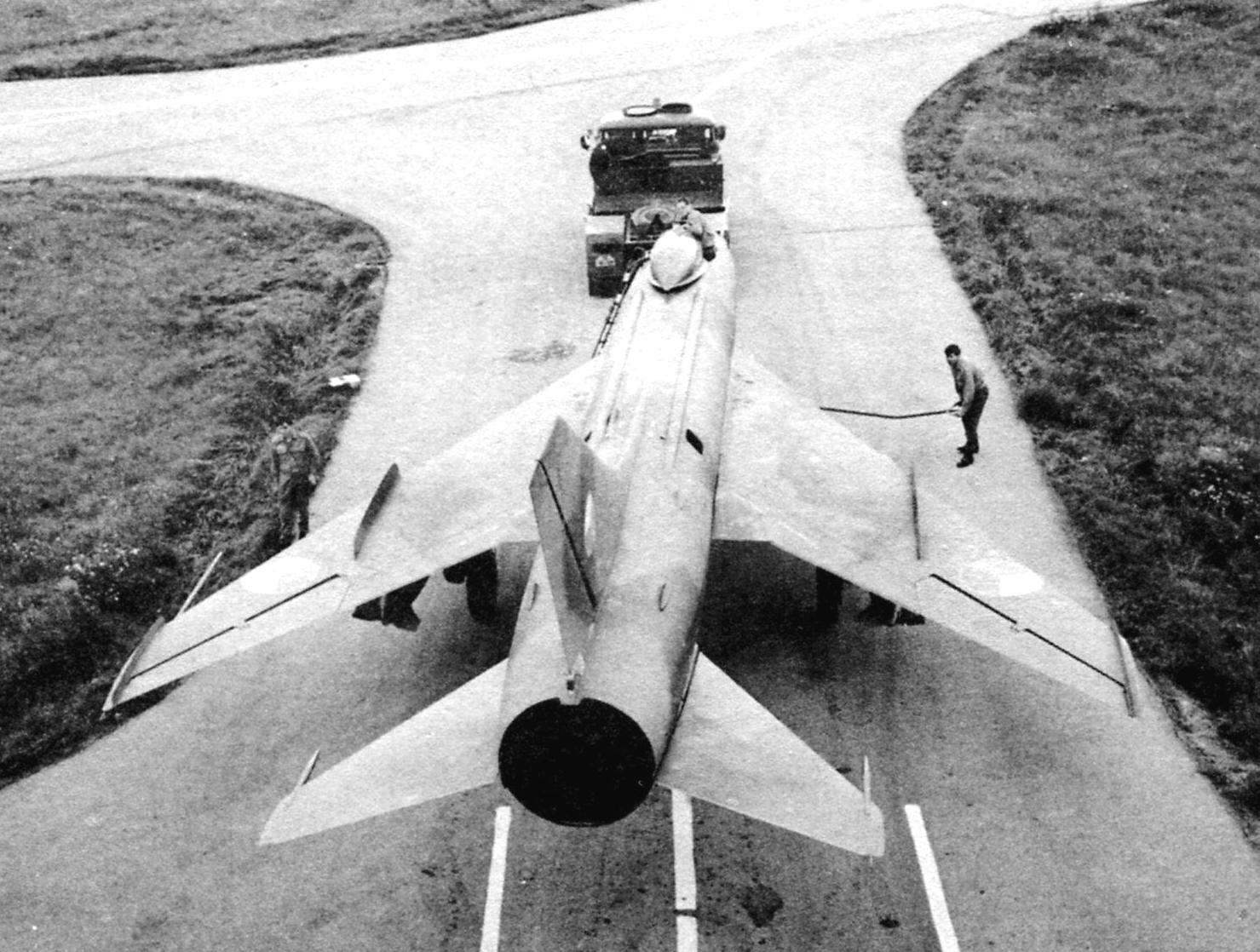
Su-7B – road at the start
Powerplant. The plane is equipped with a turbojet engine AL-7F-1 with afterburner. Engine length – 6630мм, max. diameter – 1250 mm, weight – 2010 lbs. Maximum thrust besforsazhny mode – 6800 kgf, kgf afterburner -9600. The compressor of the engine axis with a nine-stage supersonic inlet, with a constant (uncontrollable) an annular bypass air on the 1st stage, with rotary guide vanes 1st stage and managed (via tapes) by-pass air for the 4th and 5th stages of the compressor. The main combustion chamber – annular, two-stage turbine. Afterburner camera with extension tube and adjustable jet nozzle.
Starting system – Autonomous. The engine starts with the turbostarter TS-20, spins the motor starter, ST-SMT. As a start-up fuel used gasoline B-70. Emergency start of engine in the air is the same system that run on the ground.
Cooling of the afterburner, the extension tube and the drive unit of the engine and the turbostarter is the outer air taken in through air intakes located on the surface of the fuselage.
System using supplemental oxygen is used to run the engine at high altitude, start the engine on the ground at a low temperature, and to start the afterburner.
The fuel used is kerosene grades T-1, TS-1 or a mixture thereof. The fuel is placed on a plane in four fuselage fuel tanks, two wing tanks sealed-compartments and two external fuel tanks (PTB). The full capacity of the fuel system, including overhead bins, 4695 liters, of which: tank No. 1 – 1100 liters in tank No. 2 – 680 l, tank No. 3 – 505 l, tank No. 4 – 330 l, two wing tanks-compartments – 800 l in two tanks suspended – 1280 L. System fuselage tanks are loaded through the neck in the tanks № 1 and № 3, and each of the wing fuel compartments and overhead bins – using the available neck.
The hydraulic system of the aircraft provides the extension and retraction of landing gear, flaps, brake flaps, the cone inlet, anti-surge valves, power actuators (boosters) control stabilizer, the ailerons and rudder. The hydraulic system consists of three separate systems: a power booster and two – main and backup. The maximum pressure in the hydraulic system -215 kg/cm2.
The pneumatic system of the aircraft ensures the braking of the wheels and emergency landing gear and flaps. The pneumatic system consists of two self contained pneumatic system: main and emergency. The pressure in the cylinders is 150 kg/cm2, in the Executive mechanisms – 12 kg/cm2.
The electrical system provides power supply of consumers of direct and alternating currents. All aircraft performed in a single-grid scheme attach the negative wire to the body of the plane. The main sources of electricity on a plane are a constant current generator GS-12T and the alternator JLG-7.5 B. Emergency DC source is a rechargeable battery 12SAM-28.
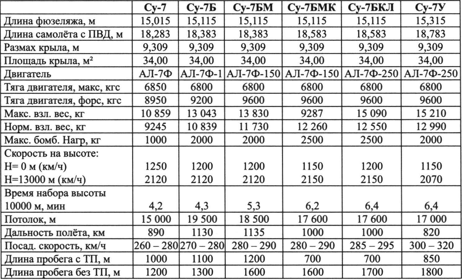
THE MAIN PERFORMANCE CHARACTERISTICS OF THE AIRCRAFT SU-7
To connect on-Board power supply of aircraft to land-based sources of electricity there are two forks of the airfield power supply: one ШРА400МЛК to supply a constant current, the other ШРА200ЛК – variables.
Avionics.
It is composed of: SPO “Sirena-2” (station warning receiver of the plane by the enemy from the rear hemisphere), and coherent radio VHF RSIU-4V “Almond”, radio compass ark-5, marker radio receiver MRP-56П, radar transponder, SRO-2, airborne the defendant SOD-57M, radar rangefinder SRD-5M, the autopilot AP-28И1 and artificial horizon AGI-1.
Weapons. Built-in armament consists of two fixed guns, HP-30 ammunition 80 rounds per gun.
Suspension arms includes:
- unguided missiles s-21, S-24, S-5 in blocks UB-32, UB-16 and guns ORO 57КМ missiles-ZK on APU-14U;
- gun mount UPK-23-250 ammunition 250 shells;
- bombs caliber 50, 100, 250, 500 kg;
- a nuclear bomb RN-28.
All aircraft weapons are designed to operate against ground or surface targets. Missiles s-ZK, S-5, built-in gun and gun mount UPK-23-250 can be applied and air targets.
At the same time be suspended under the aircraft unguided missiles and bombs is not recommended, on the basis of differences in the tactics they use and the desire to reduce the time spent on the plane over the target.
N. Food reserve was, A. CHECHIN
Recommend to read
 SAILBOAT… ON THE TRUNK OF A CAR
Still quite recently it seemed that forever passed away, imbued with romanticism, but proved impractical in our rationalistic age, the legendary tall ships of the past centuries — a... AND COLORS YOUR HOUSE
In houses with thin walls, window sills, as a rule, a narrow Board, on which fits is that of a matchbook. Therefore we have to build the colors of the shelves, stands and other fixtures...
