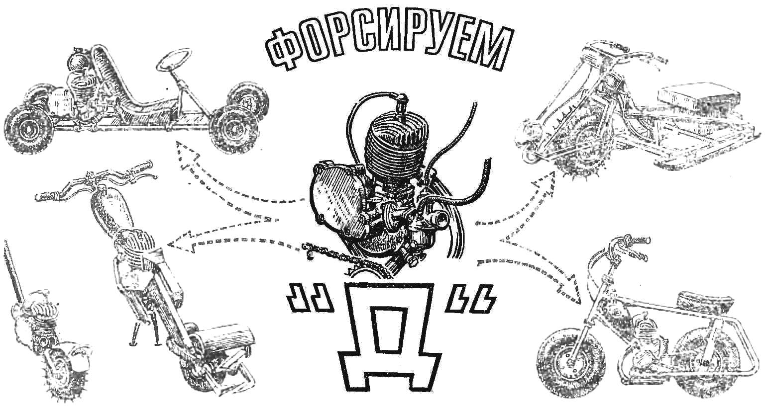
 Bike engines D-5 is familiar to many designers and Amateurs. On their basis build different machines: microvesicle and motology, microaerobic and motonarty. Often readers turn to us with questions about the increase in power bike engines. We will try to describe the main methods of speeding up the engines D-5 and D-6 (to try to force the engine D-4 is not recommended, as this will require significant additional alterations, replacements, cylinders, crankshaft and other parts).
To expose the modernization of the new features the engine. The most accessible method of speeding up — increasing the compression ratio (the compression ratio of the serial motors D-5 and D-6 equal to 8). By means of an active cylinder group to increase the geometric compression ratio of more than 9 should not be, because at higher rates the engine quickly overheats and there is a jamming of the piston. To increase the compression ratio must be machined seatings of the cylinder and cylinder head, as shown in figure 1. This will allow you to bring the compression ratio to 8.6—9. After installing rebuilt heads on the engine be sure to measure the volume of the combustion chamber that will allow to adjust the degree of compression. This will secure the motor so that the cylinder was in a vertical position, install the piston in the upper dead point and fill the combustion chamber spindle or motor oil from a syringe or graduated cylinder to the middle thread of a candle.
The compression ratio is calculated by the formula:
E=(Vh+Vc)/Vc
where Vh — working volume of the cylinder, Vc is the volume of the combustion chamber defined by the amount of oil poured into the plug hole (cm3), E is the geometric compression ratio.
The final value of compression set with strips of annealed red copper or soft aluminum. The head of the cylinder should be lapped at the landing place.
The described method of forcing is the simplest. It gives a gain of about 0,11 HP Further increase in power is achieved by changing the phases of intake, bypass and release, production of several new parts, replacing the carb and exhaust pipe. Diagram of the recommended timing of the Cycling of motors is shown in figure 2.
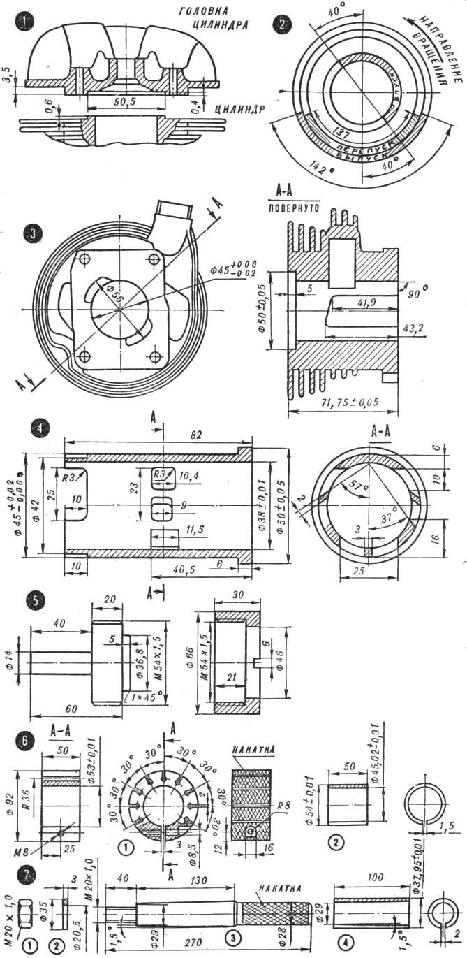
Fig. 1. The drawing of the bore of the cylinder head.
Fig. 2. Diagram of valve timing.
Fig. 3. Upgraded shirt of the cylinder.
Fig. 4. New cylinder liner.
Fig. 5. Mandrel for milling cylinder left holder, right — nut.
Fig. 6. Outside lap for cylinder liner:
1 — bar (D16), 2 — ring lapping (cast iron).
Install the specified phase is possible only when a thorough alteration of the engine. To take the case to an inexperienced person should not be — the engine will probably be ruined. The described method requires good machining equipment and high qualification of the contractor. The sequence of operations is as follows. First of all protectives shirt of the cylinder to the inner diameter 45,0-0,02, as shown in figure 3. While the factory cylinder liner is removed. Seat flange of the cylinder jacket face piercing holes, strengthening the shirt on a cylindrical mandrel. This ensures a strict perpendicularity of the axes of the holes of the sleeve and plane seats. The purge channels in the jacket of the cylinder should be increased in accordance with the drawing.
Drawing a new cylinder is shown in figure 4. For its production suitable antifriction cast iron brand (СЧ40-60, SCH21-40). The technology of manufacturing the following: grind the workpiece with an allowance for inner and outer diameter 0.5—0.8 mm and is marked inlet ports, then by installing the workpiece in a special holder (Fig. 5), milled in accordance with the dimensions shown in the drawing. Clamping the workpiece directly in the Chuck dividing head of the machine impossible, for the inevitable deformation of the part. Milled face piercing holes, a sleeve on the lathe to the nominal size, and finally treated with lapping (Fig. 6, 7) using first coarse, then fine abrasive paste. You need to fillet all the sharp edges of the overflow and outlet ports with a needle file or drill, equipped with a grinding stone. Grinding sleeve on the outer diameter of the perform to provide a sliding fit (heated to 70-80° shirt cylinder sleeve must log tight, but efforts).
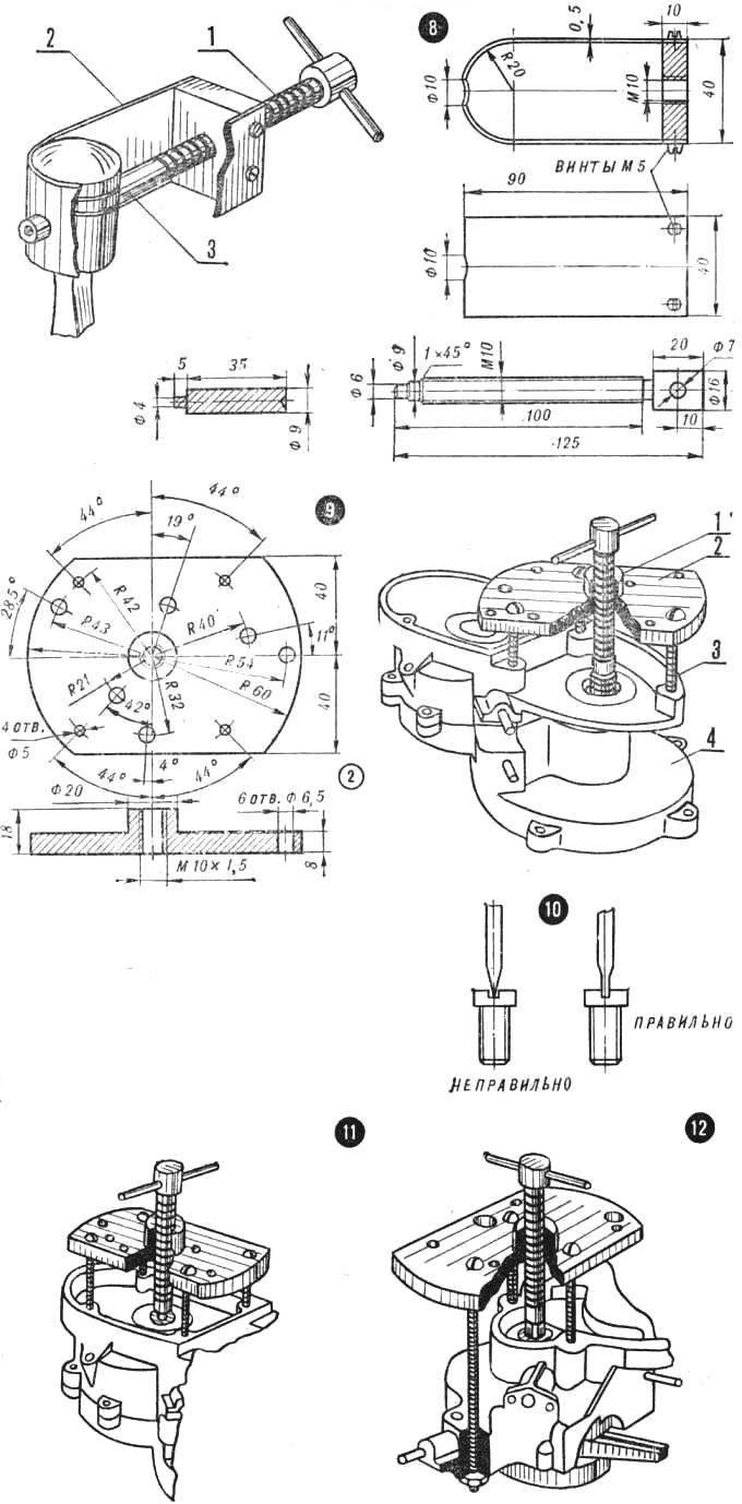
Fig. 7. The internal lap for the sleeve:
1, 2 — nut and washer, 3 — mandrel (St. 45), 4 — sheave (cast iron).
Fig. 8. Puller for piston:
1 — screw (Art. 45), 2 — clamp with nut, 3 — mandrel.
Fig. 9. The removing roller clutch puller universal:
1 — screw, 2 — puller 3 — set screw, 4 — Carter.
Fig. 10. Sharpening screwdrivers.
Fig. 11. Raspressovki halves of the crankcase.
Fig. 12. Removing the crankshaft from the right crankcase half.
The piston is made from aluminum alloy grade AL-26 or AK-4-1, trying to accurately reproduce the dimensions of the factory part. While it is preferable to manufacture by machining (workpiece machined on a lathe followed by milling of the inner part).
Next, install a new intake phase. Before proceeding to this operation, it is necessary to disassemble the engine. It is removed from all items, as indicated in the instructions. Further disassembly is a very important operation requiring special tools. Otherwise the inevitable irreversible damage to main parts. For complete disassembly requires two homemade remover: for you-the pressing and install the piston pin and the universal (Fig. 8, 9). First remove the piston. To do this, remove the retaining ring piston pin, heat the piston to 60-80°, set the device for extrusion piston pin, as shown in figure 8, and the screw with the optional mandrel (of soft material) is extruded piston pin.
Rotating screw universal puller, as shown in figure 9, is extruded roller clutch. Unscrew all the screws, tightening half of the crankcase, first carefully clearing the slots. A screwdriver must be properly sharpened and the width of the slots (Fig. 10). Universal puller, as shown in figure 11, is extruded crankshaft from the left half of the crankcase. Then set the puller on the right half (Fig. 12) is extruded and the crankshaft. Usually vypressovyvaetsya shaft and main bearings that have to be replaced, because to remove them from the axles shaft is possible only by destroying the separators.
(To be continued)
Recommend to read
 LEASH FOR TRANSOMS
To open the window, crashed from a random gust of wind, usually set PA frame hooks or restrictive straps with a number of slots. However, the "hobbled" so the Transom is trying to "free"... DURABLE TENT
Undoubtedly of interest to many tourists are the publication of the journal "modelist-Konstruktor". But they mainly describe the various vehicle designs and less emphasis on other...
