
 The car’s handling and tyre wear, as we know, primarily depends on the state of the front suspension of corners of a longitudinal inclination of axes of rotation, and angles of camber and toe. As a rule, adjustment of all these parameters produce on special stands at service stations, but in this case it is not always the adjustment will be optimal for a specific vehicle and specific conditions.
I was able to develop and implement a scheme of adjusting the front suspension, which is quite good for RWD cars such as Mercedes or “Moskvich”.
The control scheme depicted in the figure. Before starting work check the condition of the upper and lower ball joints, silent blocks, joints, steering rods, steering column, and if defects are found, be sure to eliminate them. The vehicle should be on a horizontal surface over a viewing hole so that was free access to the front wheels inside and out.
Technical instruction it is recommended to make adjustment of the front axle at full static load (for two people or 150 kg of cargo on the front and rear seats) and a fully filled tank. It seems that this recommendation does not correspond to the real conditions of the vehicle. The fact that the private car the lion’s share of time is operated at a load of 1 -2 person. Therefore, before carrying out adjustments of the front axle evenly distributed on the front seat bags with gravel or sand, 25 kg each—three bags on each chair. If the tank is not fully filled, should compensate for the additional mass of the fuel load. Be sure to check the air pressure in tyres and if necessary finish it to norm.
Control and adjusting of the front suspension is made in the following sequence:
1—adjust the position of the rear axle relative to the body (axis) of the vehicle (the dimensions of OG and OV in the figure);
2—adjusting the mutual arrangement of the rear axle and front suspension (the size of the BH and BV in the figure);
3—adjustment of corners of a longitudinal inclination of axes of rotation (View A);
4—adjustment of the camber angles of the wheels (Type B);
5—adjust the toe-in (sizes L and l).
Notice that the adjustment parameters, marked with points 1 and 2 is carried out only in the case that produced the removal or replacement of the suspension elements (eg; springs, leaf springs, longitudinal and transverse jet rod) or after suspension of the car had a strong impact on the potholes, which the car started to “pull” to one side. These operations are made using the made of curtain pipe by sliding line (with knives at its ends) by comparing the dimensions of OG and OV, AG and BV. If different from each other by more than 2 mm—adjustment is necessary. Points A, B, C, d—extreme symmetrical points on the front suspension and the rear axle, the point O is the geometric center between the points A and B.
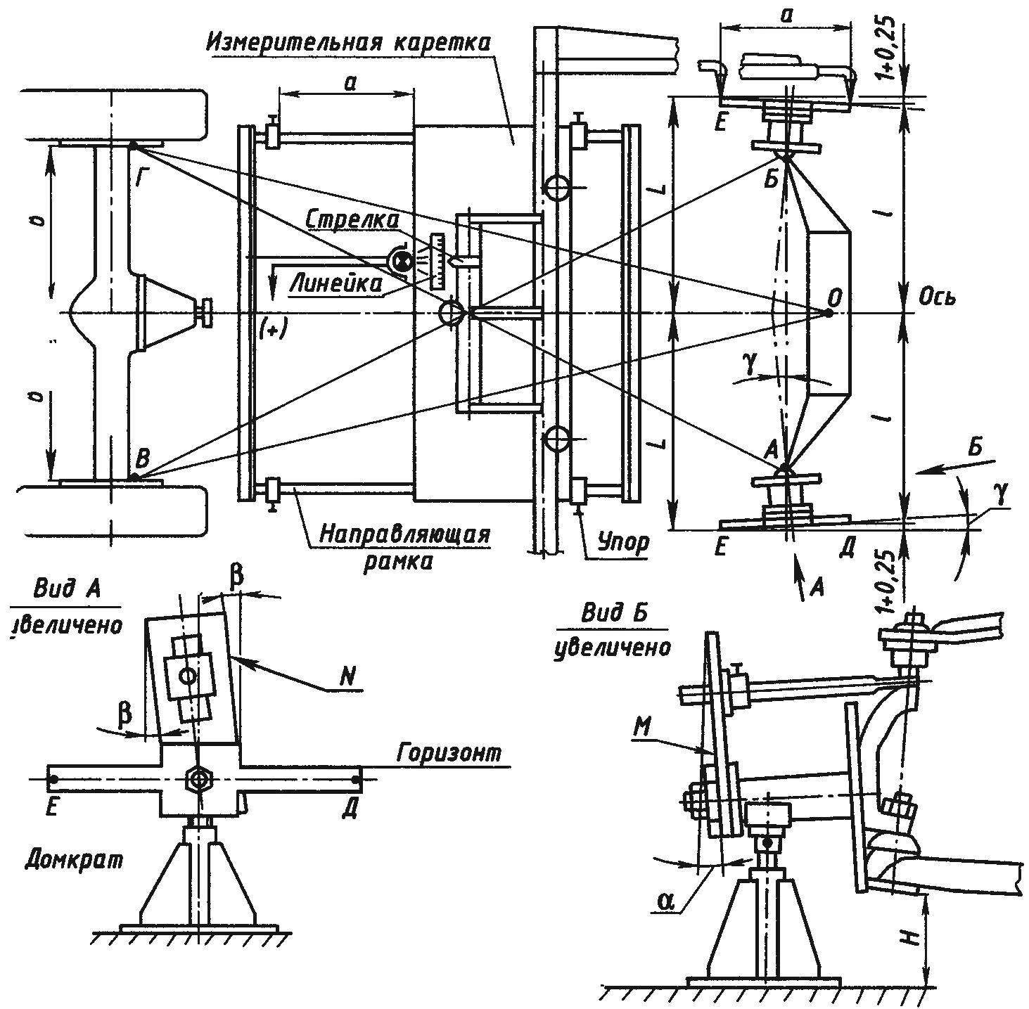
The scheme of adjusting the angles of descent and camber of the front axle on the car
Before adjusting the parameters, indicated by paragraphs 3, 4 and 5, it is necessary to pump the front suspension a few times to press his hands on the bumper to the suspension arm took a middle position. After that, the measurement is made on each side of the N variables (View B) from the floor to the lower arm and made a test stand (wood, metal) with height H for each side. These racks may not be the same, which speaks of different degrees of wear of the lower ball joints and tires.
The rear wheels are fixed on both sides stops. Then removed the front wheel, hub and axle of the rotary axle device is installed, and below them the jacks. By rotation of the screws of the jacks lower arms are exhibited on the floor on the value of N (check with a test stands). Re-pumped front suspension. With the help of goniometer with a measurement accuracy 0°6″ measured actual values of the angles α and β, for which the protractor is applied alternately to the planes M and N.
Then count how many of the adjustment brackets and plates must be removed or set on each side, then install (remove) them and re-measurement defined by a new (desired) values of these angles.
Control of toe is performed by measuring a movable carriage that is moved along the guide rails, exposed along the axis of the car.
The adjustment consists in changing the lengths of the steering rods. Before Assembly it is necessary to make a careful balancing of the wheels, and then perform a control-in horizontal stretch of road, and in the absence of crosswind.
The performance of the above scheme is more time-consuming in comparison with others, however it is more accurate and, as a consequence, you will significantly reduce tyre wear and improve vehicle handling.
V. TOMASENCO, mechanical engineer, Kirovograd
Recommend to read
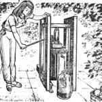 Vitamin jack
In our middle latitudes, there are years when fruit trees stand as if in construction scaffolding: they are not visible due to a palisade of supports saving branches overloaded with... SO IT WILL BE SAFER
In the video monitor МС6105 it makes sense to replace the output transformer of lines TCDS-8 to a strong — TVs-90П4 with the use of voltage multiplier. Despite the absolute similarity of...
