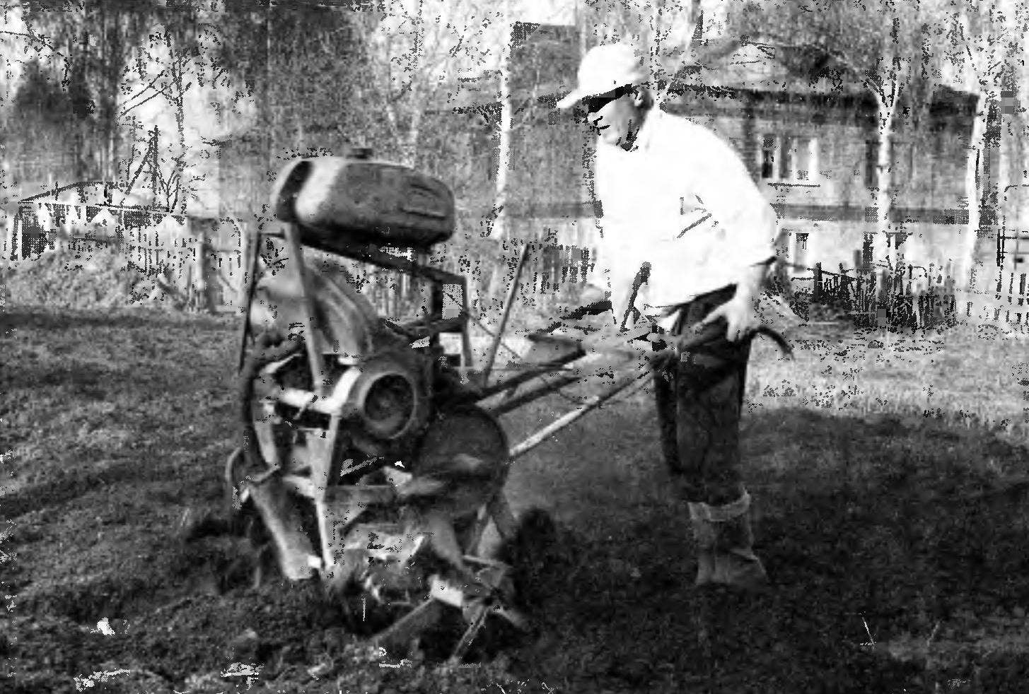
 Each year, digging up kitchen with family land on the plot where the tractor was simply not to turn, thought: “I Need a walk-behind tractor-tiller”. Of course, you can deny something else, by such a mechanism. But, Thinking about what it will be used only a few days a year, this option was considered unprofitable and, therefore, unacceptable. And then decided to make a walk — behind myself!
Readers are not judged strictly the creature of my hands, I will say that although I nurtured this idea for several years, made motomizu just a few weeks before the spring harvest, from what was at hand. Immediately after making motomizu experienced: has performed with its help the necessary amount of work. And although I myself something didn’t like in the appearance of the machine to alter anything did not, considering that the main thing in it all the same reliability and performance rather than attractiveness.
Walking tractor frame welded, spatial, quite intricate (one might say, even indefinite) configuration. It happened because its elements are customized to fit the layout of the power unit and transmission, and the items made from the material that was at hand — rolled steel of various sizes (angles, round and rectangular tubes, etc.).
I’ll note that the picture here is not a blueprint, but rather a schema of the frame with approximate dimensions, and much was done “in place”.
The upper part of the frame is a kind of a stretcher strut for the fuel tank, which is mounted on the engine. Because gasoline in the carburetor is fed by gravity.
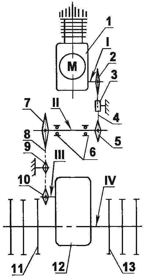
Kinematics motores:
1 — power unit; 2 — an asterisk of the output shaft (z = 22); 3 — tensioner roller (polyurethane foam); 4 — chain 1-tier (single row, t = of 15.07); 5, the first sprocket of the intermediate shaft (z = 22); 6 — support bearings intermediate shaft (No. 306); 7 — the second asterisk of an intermediate shaft (z = 15); 8 — tensioning sprocket; 9 — chain 2-tier (single-row, z = of 15.07); 10 — sprocket input shaft gear (z = 58); 11 — left block cutters; 12 — reducer; 13 — right block cutters; 14 — lever control motomete; I — output shaft of the transmission; II — the intermediate shaft; III — the input shaft of the gearbox; IV — bilateral output shaft of the gearbox
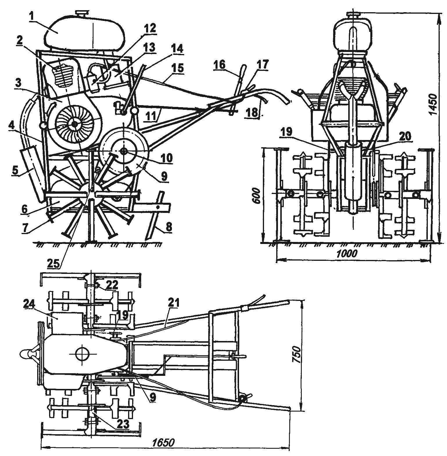
The layout of metafrasi:
1 — fuel tank (from motorcycle K-175); 2 — power unit (motorized С3Д); 3 — the system of forced cooling motors (motorized С3Д); 4 — frame; 5 — muffler; 6 — gear reducer (i = 30, from the industrial pipeline); 7 — block cutters; 8 — brake flat-blade type; 9 — sprocket of the second chain transmission (z = 58, from agricultural machinery); 10 — intermediate shaft (from the agricultural machinery, modified); 11 — pull speed switch (wire Ø5); 12 — carburetor; 13 — air filter (tractor); 14 — lever of a releaser (pipe Ø22); 15 — control cable choke carb (from a motorcycle); 16 — gear lever; 17 — coin adjustment “gas” (from the motorcycle); 18 — the lever of deenergizing of coupling; 19 — sprocket driven (machinery); 20 — the body supports the intermediate shaft with two bearings 306 (agricultural equipment); 21 — cable clutch (from a motorcycle); 22 — pin (M12,4 PCs.); 23 — output shaft gear (circle Ø42); 24 — magneto (from starting tractor engine); 25 — tensioner pulley
At the bottom of the frame, on a platform made of sheet steel, mounted reducer. The force unit is placed between them (gear) and tank, with the bottom of the crankcase is still at the lower ends of the levers arms. Thus, the arms are part of the frame. The main engine mount on the frame on regular brackets are used as a motor, from an old motorized wheelchair.
The power unit (the engine together with gearbox and clutch) is also taken from the wheelchair sidecar С3Д. I think that it is very suitable to this machine as a cultivator. First, this motor is unpretentious and works on low-grade petrol. Second, is it strong enough — it has 12 horsepower and develops a maximum power at only 3000 rpm. Thirdly, its cylinder is equipped with a regular air cooling system, without which the engine of the tillers at low speeds work normally just not be able.
Alterations of the engine is not required, but I had to replace part of its external devices. So, for example, made it to the silencer of his own design; set the air filter from a tractor (the staff probably would not have provided a good clean air in dusty conditions); replaced the handle manual start.
But the project included upgrading electrical equipment: all of the regular set were replaced by magneto from starting the engine of the tractor DT-54.
Transmission tillers-cultivator combined from different units industrial manufacturing and improvised units. The first step is the clutch and gear shift of the power unit, the second — a home-made intermediate shaft with two chain of transmissions and, finally, the third reduction gear.
First chain transmission from the output shaft of the power unit on the intermediate shaft has a leading and driven sprockets with the same number of teeth (22), that is, its transmission ratio is 1. Chain single row with a pitch of 15.07 mm from the decommissioned agricultural equipment. Her tensioner pulley machined from polyurethane. A second chain transmission from the intermediate shaft to the input shaft of the gearbox. Here sprocket has 58 teeth, and the driven — 15, i.e. the transfer increases. The circuit is the same, and the tension mechanism is a small asterisk.
Such an atypical selection of gears was due to the presence of such in the first place. And secondly, the only way was to 30-fold decrease in the number of revolutions of the gears to obtain optimal rotation of the milling cutters (26 rpm) at maximum power in first gear.
The gear — industrial production, three-stage, with cylindrical gears. It from drive a heavy plate conveyor, and therefore no problem ensures the transmission of very high torque.
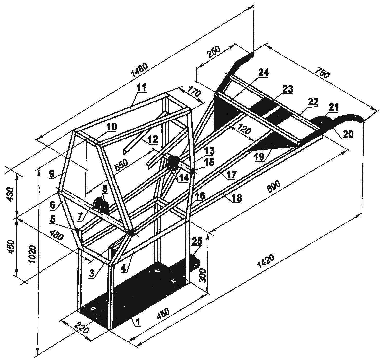
Frame (material details of all positions in addition to stressed — steel 25×25 area):
1 marketplace for gear (steel sheet s6); 2 — front pad (4 PCs), 3 — lower cross member (2 PCs); 4 — intermediate shaft support beam (2 PCs); 5 — solitaire stands (steel sheet s3. 2); 6 — front lower slant rack (2 pieces); 7 — front cross member (tube Ø44); 8 — front mounting engine (sheet s5); 9 — front upper inclined strut (2 PCs.) 10 — upper tie bar (3 PCs); 11 — fuel tank support beam (2 PCs), 12 — foot console air filter (2); 13 — rear upper strut (2 PCs), 14 — back brackets engine mounts (steel sheet s5. 2); 15 — rear (tube Ø44), 16 — rear lower strut (2 PCs.); 17 — spar (2 PCs); 18 — the control lever (tube 25×25, 2); 19 — Klondike levers (steel sheet s2, 2); 20 — arm (pipe Ø22. 2 PCs); 21 — the area of the cuff “gas” (sheet s2); 22 — screed handles (pipe Ø22); 23 — the site of attachment of the gear lever (steel sheet s2, 2); 24 — coupling levers (tube 25×25); 25 — bracket-frame sides (square pipe 70×70)
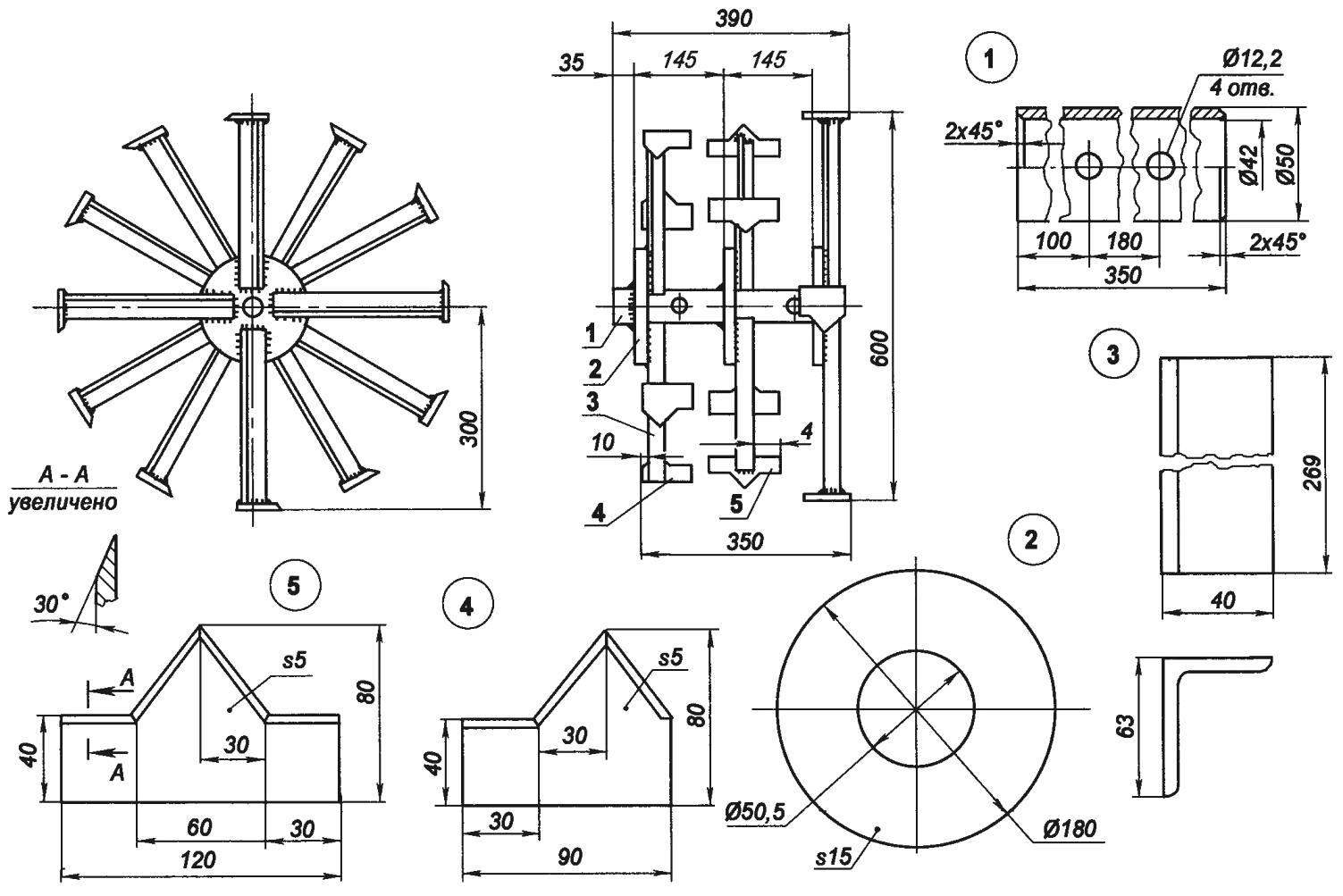
Block cutters:
1 —sleeve (pipe Ø50×4); 2 — flange (steel sheet s15,3). 3 — front knife (area 63×40,12пгг.), 4 — left knife-right—mirrored (tool steel s5 8 PCs); 5 — average knife (tool steel s5,4 PCs.)
The output shaft of the gearbox was replaced with a longer (about 1 m) two-way (also picked up from the farm) because it is simultaneously the drive shaft of the working bodies of the units of mills.
Mills combined in two blocks — 12 cutters each. Each block in turn consists of three nodes — 4 mill installed at an angle of 90° relative to each other. In addition, the position of cutters of the nodes in the blocks are offset by 30° relative to the adjacent, but because they work and move even when relocation of the unit from place to place and on solid ground rather smoothly, at least smoothly.
The cutter consists of a knife, made of 5 mm sheet tool steel, and the rack is made from a steel angle 63×40. The knife is welded to the end of reception, and the other end of the strut welded to the flange, which consists of four cutters set mutually at right angles, into a single node. The flange is in turn mounted on the bushing block and welded to it in a circle.
Bushing block made of pipe, the inner diameter of which corresponds to (or rather, a little more than) the outer diameter of gearbox output shaft (drive shaft of the working bodies). Bushing block, cutters mounted on the shaft and is fixed here the two pins from the bolts M12. Bolts-pins are inserted in holes previously drilled simultaneously in both parts — the shaft and the sleeve
Operation controls motomete: levers shifter, coin adjust throttle, clutch lever made closer to the arms of the control levers.
The velocity of metafrasi but adjustable “gas” is even and the brake pin. To slow the movement of the pin using the control levers deepens into the ground, and for faster — rising. The pin is inserted into the bracket, which is also a beam. To it is connected a plow or other tillage tool — for example, paw Lancet cultivator. Instead of the cutters can slide the wheels. In the wheeled version of the walking tractor can work as a tractor trailer truck, which is also linked to a beam.
Can not boast of the elegance of the execution, but the machine runs properly and expectations in terms of facilitating labour on the farm and do the farm justifies.
And although the design was a bit periuterine, but it is rather plus, than a minus — when you use the cultivator with the wheels as the tractor he not stalled on the dirt, even wet roads. And when the cutters are not so often and not fully use the brake.
Cutter and cultivator loosen the ground, as they say, “in tatters”, and no further processing (breaking lumps with a shovel, loosen the soil with a rake, etc.) the soil is no longer required.
V. KURAKIN, Saransk
Recommend to read
 THE AIRCRAFT FOR THE CRUISER
We can safely say that the class of the ship ejection of seaplanes was the most short-lived in the history of Soviet aviation. There are many reasons, but chief among them is that in the... LIGHT AND… FANTASY
As soon as we get a new apartment or refitting the old capital, followed by furniture there is a question of lamps. And if the industry had long ago mastered the production of sets of...
