I did not set a goal to have a cat-transformers. However, the latter two modifications at any time to convert one into another. Enough to replace front axle and tie rod (the front legs with skis remain), and the rear— wheel and driven sprockets. Yes, to tighten the chain.
Here on this third modification want to tell you more.
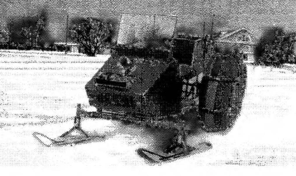
The overall look and layout of the snow:
1 — frame of the windscreen; 2 — relay controller; 3 — engine (from a motorcycle “IZH-Ju-5”); 4 — hood; 5 — muffler; 6 — battery; 7 — front bearing; 8 — tie rod, steering; 9 — the steering shaft; 10 — frame 11 — chain of the first gear; 12— bracket of the intermediate gear; 13 — chain of the second gear; 14 — chain tensioner; 15 — wheel; 16 — sprocket rear axle; 17 — bagani; 18 — chain case; 19 — steering wheel; 20 — a fuel tank; 21 — bumper; 22 — step; 23 — the driver’s seat; 24 — trailed; 25 inlet muffler exhaust; 26 — air conditioners; 27 spotlight; 28 — the handle of the hood; 29 — cat’s eye; 30— chair management; 31 — the instrument panel; a 32 — lever shaft; 33 — drum brake; 34 — a fan cover.
Snow frame (frame of the windscreen is not shown):
1 — support the fuel tank and instrument panel (area 20×20); 2 — arc of the hood (tube 26×2,5); 3 — eyelet bonnet (strip 30×3, 2); 4 — skeleton of the hood (area 20×20); 5 — bumper (tube 32×2,8); 6 — the front crossmember (tube 32×2,8); 7 — axis of rocking of the control (screw M8); 8 — solitaire (leaf s6, 2); 9 — bushing mount of the front axle (steel 20, 2); 10 — spar top (tube 32×2,8, 2); 11 —lower spar (tube 32×2,8, 2); 12 — jumper (tube 26×2,5, 20, the location is arbitrary); 13— motor; 14, 20 — floor supports (pipe 32×2,8); 15 — the case of the lower steering shaft bearing (steel 20); 16 — limiters floor (pipe 32×2,8, 2); 17,19 — cross member middle or rear (tube 32×2,8); 18 insert longitudinal (pipe 32×2,8); 21 —bracket chain tensioner (sheet s6, 2); 22 — bar mounting rear axle (strip 25×6, 4 PCs.); 23 — the bearing of the trunk (tube 26×2,5, strip 30×3, 2); 24 — the frame of the driver’s seat; 25 — hole for fastening frame to the windscreen (4 PCs.).
The frame of the driver’s seat:
1 — housing of the upper steering shaft bearing (steel 20); 2.5 mounting bracket of the intermediate gear (area 20×20, 2); 3 — arc (tube 26×2,5); 4 — loop rack (strip 30×3, x4); 6 — Bush bearing (rubber); 7, 9 — crossmember (tube 26×2,5); 8 insert (tube 26×2,5); 10 — loop fastener seats (strip 30×3, x4); 11 — loop fastener of the backrest (strip 30×3, 2 pieces); 12 — pole (tube 26×2,5, 4 pieces); 13 — bracket upper bearing (tube 26×2,5).
Intermediate gearbox (top view):
1 — nuts M8 (4 PCs); 2 — ear of the tensioner fixed (steel 20, 2); and 3.21 — ears tensioner movable (steel 20); 4 — tensioner bolt M8 (2 PCs); 5 — nut M14; 6 — short bushing spacer (tube 20×15,2, L19); 7 — 202 bearing; 8 — bearing housing 202 (steel 20); 9 — asterisk small (g= 16); 10 — hub small sprocket (steel 20); 11 — the hub of the large sprocket (steel 20); 12 — sprocket of a large (d=42); 13 — the bearing 203; 14 — sleeve long push-in (tube 23×17,2, L79); 15 — shaft (steel 20); 16 — the frame of the snowmobile; 17 — an arm of fastening of a reducer; 18 — frame chair; 19—a bolt M8 (8 PCs); 20 — gearbox mounting (steel 20, 2 PCs.).
Motor frame:
1 — holders (tube 32×2,8); 2, 5 — lugs the engine mounts; 3 — bar (pipe 32×2,8); 4 — cross member (tube 32×2,8).
Snow scooter outdoor, single, with front steering ski and the rear wheels. The engine and most of the electrical equipment placed in front of the driver’s seat. Behind the chair should be a fairly capacious trunk. This arrangement consider beneficial. First, uniformly loaded bridges, and secondly, when driving warm air from under the hood heats the driver.
From the snow there is no differential. This simplifies the design, improves flotation in the snow. Speed rolled the crust up to 50 km/h. the Machine is able to pull a sled with a load up to 200 kg.
Now let’s focus on the most important parts and components.
The largest all-in-one component — the frame. It is made in parts, which is called here as the snow frame, motor frame and the frame of the driver’s seat. In this order, and will their description.
FRAME snow collected from the water pipes. It is welded to the frame of the bonnet of the steel corners. For ease of Assembly and disassembly of the engine frame may be removable (I have it exactly like this). The engine hood that look like “Boo-ranovsky,” the light is bended from aluminium sheet and is attached to the frame in four places with screws.
MOTOR FRAME also made from water pipes. The dimensions given on the drawing and describing the relative position of ears, should be considered as indicative, since the inevitable adjustments made in accordance with the sizes of the counter assemblies is a particular engine.
The snow engine mount to the frame is attached by electric welding with the strengthening of the vertical seams of the gusset (not shown on drawings).
The frame of the DRIVER’s SEAT is already a triple service: to the front it is attached to the housing of the upper steering shaft bearing, top — seat with backrest, and the bottom intermediate gear chain transmission. The bearing housing is welded to the insert longitudinal frame; seat and backrest(the basis of their wood) is screwed with screws to the corresponding loops on the arc; gear bolts drawn to the four vertical brackets-parts.
MOTOR — motorcycle (from “IZH-Jupiter-5”) with forced air cooling. Fan — made, placed on the right engine and is driven by rubber belt from a pulley on the armature of the generator. To install this pulley was drilled removable cover of the generator and bolt the anchor to the flywheel replaced with longer ones.
Undergone minor changes, and system of engine start: kick-starter when the blowtorch was bent to at the start there was a complete revolution of the crankshaft.
Electrical snow — motorcycle, battery. Designed for 12 volt Rectifier unit borrowed from the automobile generator. Automobile and relay-regulator Р362Б.
TRANSMISSION for snow — chain two-stage. The circuit of the first stage (motor) is running between the motor and the intermediate gear, and the circuit of the second stage — between the gearbox and the rear axle.
The INTERMEDIATE GEARBOX, as already mentioned, is located under the driver’s seat and is a simple design consisting of a shaft and block of motorcycle sprockets. A large sprocket (z=42) taken from the rear wheel of the motorcycle. She cut off the “native” hub and welded on a new one, which is planted right closed bearing 203, and the left — wheel hub with a small sprocket (z=16) and the bearing 202.
The intermediate shaft of the gearbox is located in the slots of the supports and is moved by two tensioners. The exact position of the block on the shaft relative to the output sprocket of the engine are set distance sleeve. If this situation should change, then one of the sleeves can be shortened, and the other to add one or two washers.
The circuit of the second stage of transmission operate using a different tensioner located in front of the rear axle. The tensioner is a sprocket (z=42) on the hub with two bearings 203, which rotates on the axle with spacer bushings. Axis is also located in the slots of the brackets welded to the frame.
REAR AXLE is made with a solid drive shaft. This simplified the design, improved the permeability and had little effect on maneuverability of the snow — even with the grippy tires the rotation is carried out normally. The shaft rotates in two bearings 207. Their case with the glands of the skin, welded to the cheek plates of sheet steel with a thickness of 6 mm, in which there are holes for fixing to the frame the snow. To the right housing with the four screws M6 screwed disc brake pads. The disc is cut out of the housing of the driven sprocket of a motorcycle “IZH”. Brake drum of motorcycle, only protochen in the lathe outside (up to diameter 240 width 50 mm) and outside (for another hub).
The sprocket drive the rear wheels (d=60) made in a lathe from a circle with a diameter of 350 and 10 mm thick. this range was trimmed from both sides to a thickness of 6 mm and marked risk corresponding to the diameters of the pitch circles and the circumference of the projections. (The calculation is not given here since they are well-known formulas.) Taking into account the step chain was nacerdine centers and drilled 60 holes. Drill bit the diameter of the roller chain. Received teeth saw blade modified blade and a file.
The asterisk attached to the hub with eight bolts M10x1. The hub on the shaft, and brake drum is seated on a dowel. In addition, the shaft wearing three spacers.
The spokes and rims of disks of wheels are welded from steel tubes. Design of CDs is clear from the picture, so I will not linger on it. I focus only on what the picture no. To each the rim on the outside is welded by eight M8 bolts for fastening the transverse bands of segments of the conveyor belt 10 mm thick, attractive Pneumatics to about-ladies. There are still trailing bandages from a fire hose. Longitudinal and transverse braces connected at the point of its intersection by special bolts. The ends of the bolts with nuts facing outward and serve as ground-or, rather, negoziazioni wheels.
STEERING. The steering shaft is a vertical steel pipe with a diameter of 32 mm, rotatable in two bearings with rubber bushings. Upper end of the shaft is worn the wheel of the scooter “Electron” (with the sector “gas” of a snowmobile “Buran”), and to the bottom is welded a Pitman arm made of rod Bicycle pedals. The bipod is attached to the longitudinal steering rod going to the bellcrank on the frame snow. In turn, rocking the leash is connected to the tie rod of the front axle. The leash and all thrust here, with the tips having two degrees of freedom.
The chain tensioner (rear view):
1 — the frame rails; 2 — bracket tensioner; 3 — ear movable (steel 20, 2); 4 — bolt M8 (2 PCs); 5 — axle (steel 20); 6 —
nut M16 (4x); 7 — spacer long (tube 23×2,8, L246); 8 — bearings 203; 9 — wheel hub (steel 20); 10 — sprocket (z=42); 11 — short bushing spacer (tube 23×2,8, L128).
Front axle:
1 — sleeve (steel 20, 2); 2 — bandage (band 60×3, L220, 2); 3 — beam (pipe 42×5); 4 — fastening screw (2 PCs.)
FRONT AXLE — easily removable, is a tube with a diameter of 42 mm is welded in the upper part screws for attachment to the frame of the snow. To the ends of the tube welded to the vertical sleeve, reinforced bandages — strips of sheet steel with a thickness of 3 mm.
The sleeve is inserted borrowed from the Bicycle together with bearings front forks. Behind them are welded Pitman (connecting rod Bicycle pedals), and bottom bushings of the hinges attached thereto with homemade links and shock absorbers of bike “Voskhod-2M”.
SKI snow consist of a steel framework and nylon bases, connected by studs and tubes on the nose (for strength). The base obtained from nylon tubes with a wall thickness of 10 mm as follows: first, I cut out of the pipe with an ordinary saw for tree harvesting. To straighten them heated throughout its length with a blowtorch, put between two thick boards and crushed the cargo. When the workpieces have cooled down, I again warmed their noses, bent as necessary, and cooled with water. Skis with such a Foundation, have a very good slide.
In the figure it is seen that skis have undercuts. Each of them consists of two bars with diameter of 6 mm, is screwed to the ski bottom.
Steering control scheme:
1 — right support fork (left fork is conventionally not shown); 2 — fry forks; 3 — tie rod, steering; 4 — pivot linkage; 5 — lead and 6 — pin frames; 7 — rocking chair; 8 – thrust steering longitudinal; 9 — lever shaft; 10,12 — bearings of the steering shaft; 11 —the steering shaft; 13—the wheel (scooter Elektron).
Rear axle:
1 —nut М24х1,5 (2); 2 — dowel cylindrical (Ст6, rod Ø6, L50, 2); 3 — a nave of the left wheel; 4 — shaft (steel 20); 5 — bushing spacer side (tube 45×4,5, L94); 6 — oil seal (leather, 3 pieces); 7, 18 — bearing (steel 20); 8 — bearings 207; 9 — bushing spacer (steel 43×3,5, L285); 10 — M10 screw (8 PCs); 11 — an asterisk (ST5, z=60); 12 — hub sprockets (steel 20); 13 — shear prismatic (Ст6, 10x8x85); 14 — drum brake (from a motorcycle “IZH-Ju-5”, trimmed); 15 — drum hub (steel 20); 16 — disc brake (from a case driven sprocket of the motorcycle “IZH-u-5”);’ 17 — screw M6 (4 PCs.); 19 — the hub of the right wheel; 20 — cheeks mounts (steel 20); 21 — hub remote (pipe 43×3,5, L36).
The trunk:
1 — frame (aluminum, angle 30x30x3); 2 — panel case (aluminum, sheet s2); 3 — rivet (aluminum, Ø3).
Disc wheel:
1,2 — rims (pipe 20×2); 3 — spoke slant (pipe 20×2, 4 pieces); 4 — spoke direct (pipe 20×2, 8 pieces); 5 — cradle (pipe 20×2, 8); 6,7 — cheek (sheet s6);
8 — wheel hub (steel 20).
Front support:
1 — the base of the ski (nylon); 2 — jumper (area 20x20x3); 3 — amplifier (tube 15x 1, 2); 4 — frame (the area 20x20x3); 5 —absorber (motorcycle “Voskhod-2M”); 6 — stud of fork (front fork of a Bicycle, cropped); 7 — fry unlce (rod pedal bike, clipped); 8 — leg level (square 24); 9 —bracket, front (steel 20); 10 — bolt M12 (4 PCs.); 11 —rivet (23 pieces); 12 — lugs of the shock absorber (steel 20); 13 — leg fork; 14 — bushing, hinge (steel 20); 15 — washer (brass, 4 pieces); 16 — the holder of the link (bandwidth 24×4); 17—nut MB mounting podraza (4 PCs); 18 — extension frame (sheet s); 19 — magazine of the ski (strip 50×3); 20 — Bush levels (steel 20); 21 —undercut (rod Ø6, 2 PCs.).
Tie rod:
1 — adjustable fork (steel 20); 2 — thrust (rod Ø23); 3 — pin (rod Ø10); 4 — fork unregulated (steel 20).
Muffler.
The MUFFLER is welded from steel sheet 1.5 mm thick. it is inserted Inside a mesh baffle to reduce exhaust noise.
BRAKE – foot-operated, wheel-drive. The pedal (it’s under the right foot of the driver) borrowed from scooter “Electron”. From it to the brake pads of the rear axle is of two-pull rod with a diameter of 7 mm.
Of course, the design of my dream-hokata far from ideal. And I continue to improve it. Plan to soon instead of the intermediate transmission to establish the reverse gear, to increase the width of the ski. And I want to ride this car in the summer, although no differential. Of course, skis replaced the front wheels and the rear lugs will be removed for better maneuverability.
A. KLIMENKO,
Primorsky Krai
Recommend to read “BURAN” WOULD BE SAFER In the design of the transmission of a snowmobile "Buran" has a centrifugal accelerator, the CVT. During intensive operation of the snowmobile this node will wear out within two seasons.... “TRACTOR”, WHICH DOES NOT PLOW The car was built in the days when I realized that the promised "reformers" two cars in exchange for vouchers, not only to me but also most Russians have never get. While we had to work...