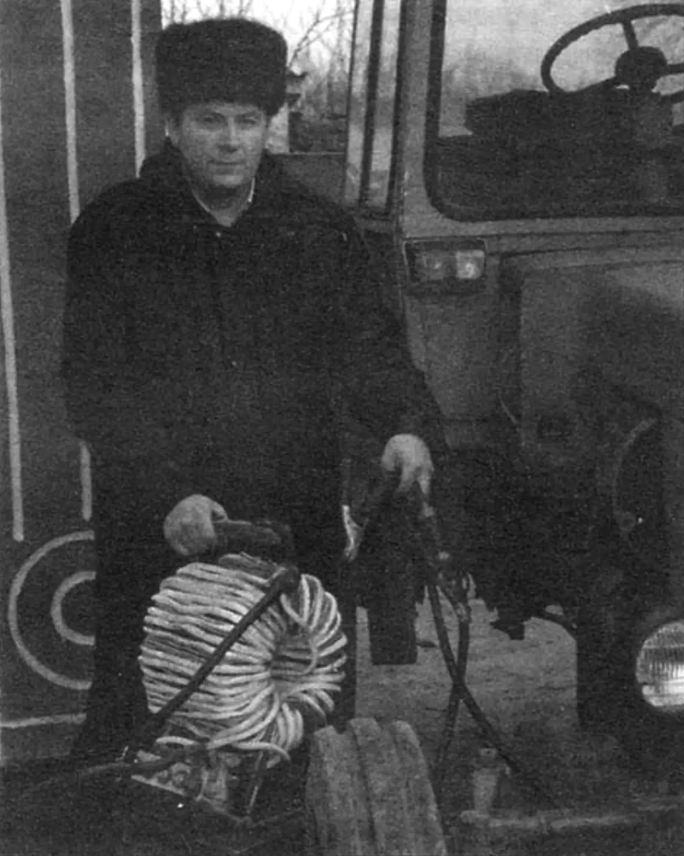
Starting a car’s internal combustion engine in winter — especially after a long period of inactivity — is often a serious problem. The issue is even more pressing for powerful trucks and agricultural machinery, much of which is now privately owned and is typically stored outdoors without a garage.
And the cause of a difficult start is not always an aging battery. Its capacity depends not only on service life but also on the viscosity of the electrolyte, which, as is well known, thickens as the temperature drops. This slows down the chemical reaction and reduces the battery’s current in starter mode (by approximately 1% for every degree of temperature decrease). As a result, even a new battery loses a significant portion of its cranking power in winter.
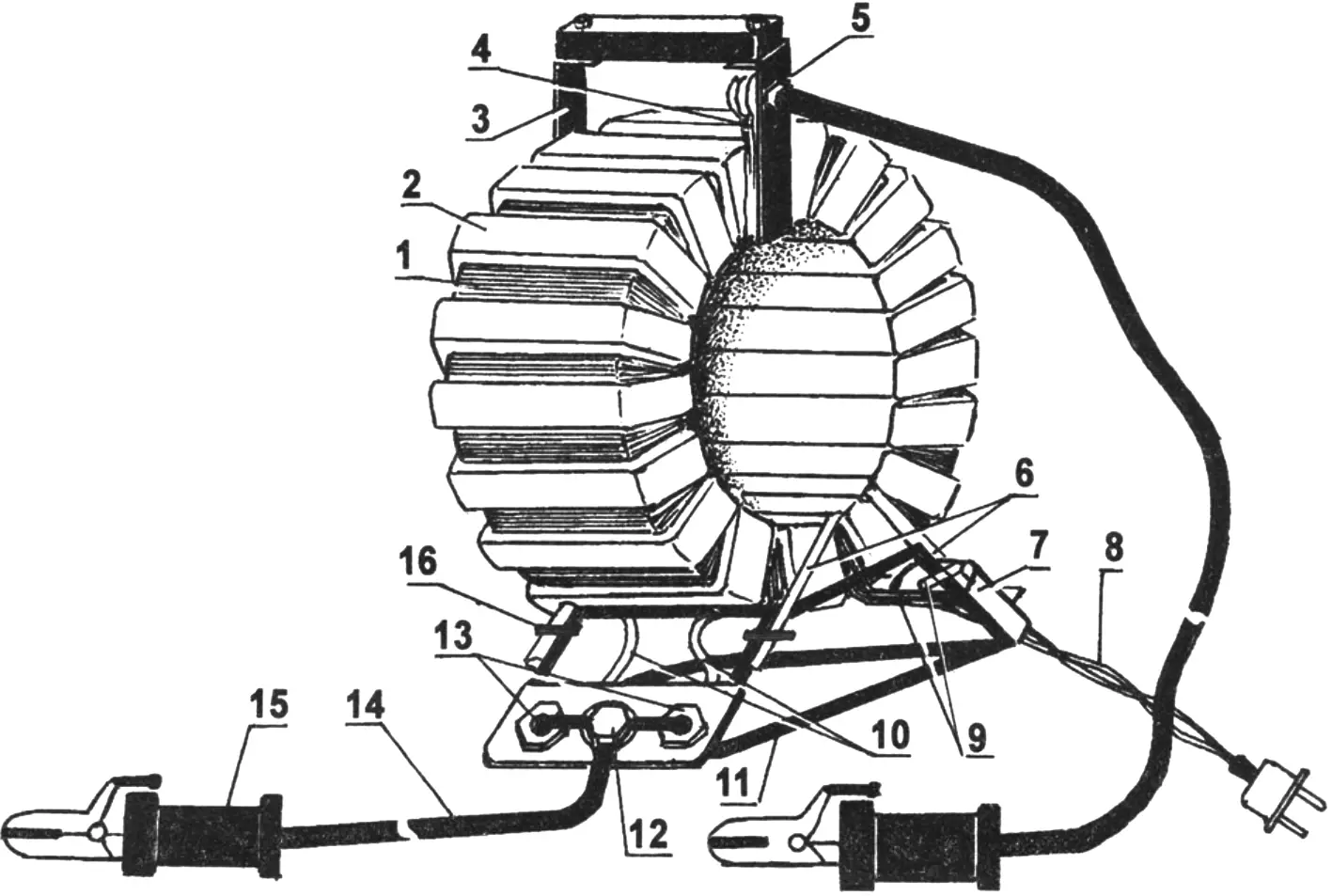
1 — primary winding (copper wire PETV Ø2.12); 2 — secondary winding (aluminium busbar Scross = 36 mm2); 3 — handle with wooden grip (steel strip 20×3); 4 — common output of the secondary winding; 5 — positive terminal (bolt M10); 6 — transformer mounting brackets to base (steel rod Ø7 wrapped in glass cloth impregnated with epoxy resin, 2 pcs.); 7 — mains switch with built-in thermal protection (type AE-1031); 8 — mains cord with plug; 9 — mains leads of the primary winding; 10 — outputs of the secondary winding; 11 — base (steel rod Ø7); 12 — negative terminal (bolt M10); 13 — rectifier diodes (type D161–D250); 14 — supply wire (multi-strand copper wire Ø12 in rubber insulation, 2 pcs.); 15 — clamp with handle (pliers, 2 pcs.); 16 — bracket-to-base connection (wire twist, 4 pcs.)
To protect myself from the hassle of starting a car engine in cold weather, I built a starting device (SD).
Its parameters were calculated using the method described in reference [1].
The operating current of the battery in starter mode is: Iop = 3 × C (A), where C is the nominal battery capacity in Ah.
As is known, the operating voltage across each cell must be no lower than 1.75 V, meaning that for a six-cell battery the minimum operating voltage Uop will be 10.5 V.
Power delivered to the starter:
Pst = Uop × Iop (W)
For example, if a car is fitted with a 6ST-60 battery (C = 60 Ah), Pst will be 1890 W.
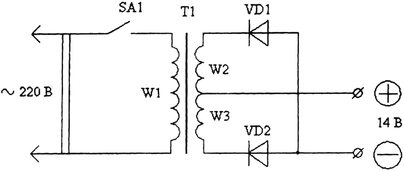
Based on this calculation and the circuit shown in [2], an SD of the appropriate power was built.
However, experience with it showed that calling the device a “starting unit” was only partly accurate. It was capable of working only as a “jump-starter” — i.e., in conjunction with the car’s battery. In low ambient temperatures, starting the engine required a two-step process:
— charging the battery for 10–20 seconds;
— jointly cranking the engine (battery and device together).
An acceptable starter speed was maintained for only 3–5 seconds, after which it dropped sharply. If the engine had not started by then, the whole process had to be repeated — sometimes several times. This is not only tedious but also undesirable for two reasons:
— first, it causes the starter to overheat and wear out faster;
— second, it shortens the life of the battery.
It became clear that the only way to avoid these problems was for the SD to be powerful enough to start a cold engine without any help from the battery.
It was therefore decided to build a different device that would meet this requirement. This time the calculation took into account losses in the rectifier block, the supply wires, and even on contact surfaces at joints where oxidation might occur. Another factor was also considered. The operating current in the primary transformer winding during engine starting can reach 18–20 A, causing a voltage drop of 15–20 V in the mains supply wires. Thus, instead of 220 V, only 200 V would be applied to the primary winding.
According to the new calculation using the method in [3], and accounting for all power losses (approximately 1.5 kW), the new SD required a step-down transformer with a power rating of 4 kW — nearly four times the starter’s rated power. (Similar calculations were carried out for devices intended to start engines in various vehicles, both petrol and diesel, and even those with a 24 V on-board network. The results are summarised in the table.)
At these power levels, a crankshaft speed of 40–50 rpm for petrol engines and 80–120 rpm for diesel engines is achieved, which guarantees reliable starting.
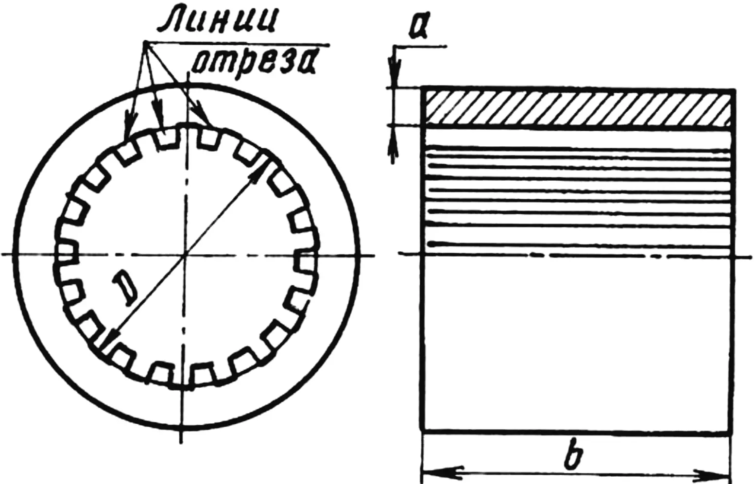
The step-down transformer was wound on a toroidal core taken from the stator of a burnt-out 5 kW induction motor. Cross-sectional area of the magnetic core: Sst = a × b = 20 × 135 = 2700 mm2 (see Fig. 2).
A few words about preparing the toroidal core. The motor stator is stripped of the remaining winding and its teeth are chiselled off using a sharp cold chisel and hammer. This is not difficult because the iron is soft, but safety glasses and gloves should be worn.
The material and design of the handle and base of the SD are not critical, as long as they serve their purpose. My handle is made from a steel strip 20 × 3 mm in cross-section with a wooden grip. The strip is wrapped in glass cloth impregnated with epoxy resin. A terminal is mounted on the handle, to which the primary winding lead and the positive cable of the starting device are later connected.
The frame-base is made from a 7 mm diameter steel rod in the form of a truncated pyramid, of which the rods form the edges. The device is then clamped to the base by two U-shaped brackets, which are also wrapped in glass cloth impregnated with epoxy resin.
A mains switch is fixed to one side of the base, and a copper plate carrying the rectifier block (two diodes) is fixed to the other side. The negative terminal is mounted on the plate. The plate also serves as a heat sink.
The switch is type AE-1031, with built-in thermal protection, rated at 25 A. Diodes are type D161–D250.
The assumed current density in the windings is 3–5 A/mm2. The number of turns per 1 V of operating voltage was calculated using the formula: T = 30/Sst. The number of turns in the primary winding was: W1 = 220 × T = 220 × 30/27 = 244; for the secondary winding: W2 = W3 = 16 × T = 16 × 30/27 = 18.
The primary winding uses PETV wire with a diameter of 2.12 mm; the secondary uses an aluminium busbar with a cross-sectional area of 36 mm2.
First, the primary winding is wound, distributing the turns evenly around the entire circumference. It is then connected via the mains cord and the no-load current is measured — it must not exceed 3.5 A. It is important to remember that even a slight reduction in the number of turns will significantly increase the no-load current and, accordingly, reduce the transformer and SD output power. Increasing the number of turns is also undesirable, as it reduces transformer efficiency.
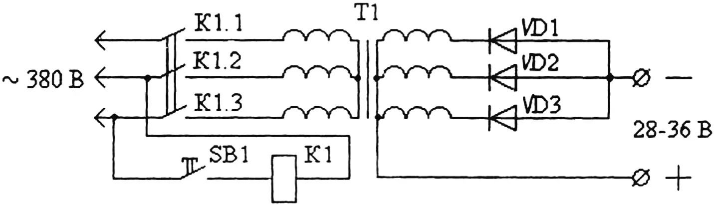
SB1 — push-button switch (types KU-121-1, KU-122-1M); K1 — magnetic starter (types PML-4000, PMA-4000); VD1, VD2, VD3 — rectifier diodes types D161–D250; T1 — three-phase transformer 380/36 V; K1.1, K1.2, K1.3 — normally open contacts of a three-pole switch
The secondary winding turns are also evenly distributed around the core circumference. A wooden mallet is used during winding. The leads are then connected to the diodes, and the diodes to the negative terminal on the panel. The centre common output of the secondary winding is connected to the positive terminal on the handle.
Now, a word about the cables connecting the starting device to the starter motor. Any carelessness in making them can nullify all the effort. Here is a concrete example. Suppose the resistance Rw of the entire connection path from the rectifier to the starter is 0.01 Ω. Then at a current of Iop = 250 A, the voltage drop across the wires will be: Uw = Iop × Rw = 250 A × 0.01 Ω = 2.5 V, and the power loss in the wires will be quite significant: Pw = Uw × Iop = 625 W.
As a result, only 11.5 V instead of 14 V will be delivered to the starter in operating mode — which is, of course, undesirable. Therefore, the connecting cables should be as short as possible (L < 1.5 m) and as large in cross-section as possible (S > 100 mm2). Multi-strand copper cables in rubber insulation should be used. For convenience, the connection to the starter is made quick-release, using pliers or heavy-duty clamps — for example, the type used as electrode holders in household welding machines. To avoid confusing polarity, the handle of the positive cable clamp is wrapped in red insulating tape, and the negative in black.
The short-duty cycle of the starting device (5–10 seconds) permits its use on single-phase mains. For more powerful starters (above 2.5 kW), the SD transformer must be three-phase.
A simplified calculation of a three-phase transformer can be carried out following the recommendations in [3], or ready-made industrial step-down transformers such as TSPK-20A, TMOB-63, etc. can be used, connected to a 380 V three-phase supply and providing a secondary voltage of 36 V.
In conclusion, a few general tips and recommendations.
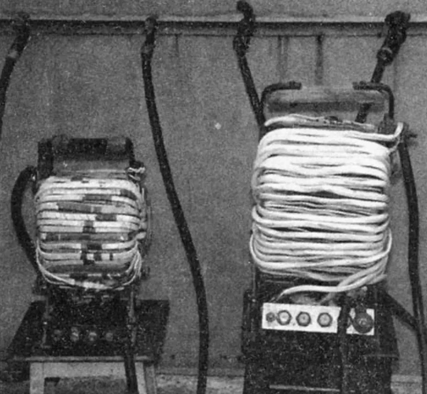
right — three-phase, left — single-phase
The use of toroidal transformers in single-phase starting devices is not mandatory and is dictated only by their better power-to-weight and size ratios (weight approximately 13 kg). However, the manufacturing process for SDs based on them is the most labour-intensive.
The transformer calculation for a starting device has certain peculiarities. For example, the formula T = 30/Sst (where Sst is the cross-sectional area of the magnetic core) for calculating turns-per-volt is chosen to squeeze the maximum possible output from the core at the expense of efficiency. This is justified by its short-duty (5–10 seconds) operating cycle. If size is not a critical constraint, a less aggressive approach can be used by calculating with the formula T = 35/Sst, taking a core with a cross-section 25–30% larger.
Required transformer power for starting devices for starters of various vehicles and tractors
| Starter type | Rated power, kW | Rated voltage, V | Used on engines | Battery type | Required transformer power, kW |
|---|---|---|---|---|---|
| ST 230A, ST 230B, ST 230K | 1.03 | 12 | Volga cars | 6ST-60 | 4 |
| GAZ-53A | 6ST-75 | 4 | |||
| GAZ-66 | 6ST-75 | 4 | |||
| ZIL-130 | 6ST-90 | 5 | |||
| ST 221 | 1.25 | 12 | VAZ | 6ST-55 | 4 |
| ST 117A | 1.18 | 12 | Moskvich | 6ST-55 | 4 |
| ST 222A | 2.2 | 12 | Tractors: T-16, T-25, T-30 | 2×3ST-150 | 6 |
| ST 142 | 7.73 | 24 | Trucks: KamAZ, MAZ, KRAZ, ZIL-133 GYa | 2×6ST-190 | 16–20 |
| ST-103A-01 | 8.2 | 24 | Kirovets tractor | 2×6ST-190 | 16–20 |
The power that can be drawn from the built SD is approximately equal to the rated power of the three-phase induction motor from which the transformer core was made.
When a powerful starting device is used in a fixed installation, it must be earthed in accordance with safety regulations. The handles of the connecting clamps must be rubber-insulated. To avoid confusion, the positive clamp should be marked — for example, with red insulating tape.
The battery does not have to be disconnected from the starter during starting. In this case, the clamps are connected to the corresponding battery terminals. To prevent overcharging the battery, the starting device must be disconnected immediately after the engine starts.
References
1. N. M. Ilyin, Yu. L. Timofeev, V. Ya. Vanyaev. Electrical equipment of automobiles. Moscow: Transport, 1982.
2. I. P. Shelestov. Useful circuits for radio amateurs. Book 1, Moscow: Solon, 1998.
3. I. Nikiforov. Simplified calculation of a mains transformer, Radio, 2000, No. 10, p. 39.
4. V. Motuzas. Electric starter, Selsky Mekhanizator, 1988, No. 4, pp. 23–24.
Modelist-Konstruktor No. 1’2007, S. GUROV
Recommend to read
 CRUISER LATIN AMERICA
To test the dynamite gun in a combat situation was not an easy task. Although auxiliary cruiser "niterói" was commissioned in late 1893 , it constantly broke down and failed, and due to... FUNNY WHEELCHAIR
Kids love to toy with them not only the room but also on the walk. Especially those that can haul on a rope or push with a thin stick. Moreover, dynamic toy when she has something...
