 Revved the motor, the motorcycle abruptly jumped up and rushed forward. The neighbouring village was what half a kilometer, as suddenly go haywire motor… to Prevent such surprises helps electronics. The bike is equipped with an electronic ignition system that significantly reduces the load on the breaker contacts, and the increase in spark energy allows the engine to work reliably in the lean combustible mixtures.
Today, motorcycle enthusiasts and is known for dozens of such schemes. Scooters with electronic ignition are available even commercially. And yet, for the designers work here no end.
In the device electronic ignition used breaker sliding contact are made of brass. The interrupter controls the ignition timing depending on the operating mode of the engine. And two-stroke engines with one or two cylinders, you can even change the direction of rotation of the crankshaft (reverse), thereby obtaining a reverse. This is especially true of motorcycle with a sidecar in off-road conditions.
Diagram of electronic ignition (Fig. 1) contains the inverter transistors T1, T2, high-voltage rectifier diodes D6, D7, thyristor КУ202М and a storage capacitor C2.
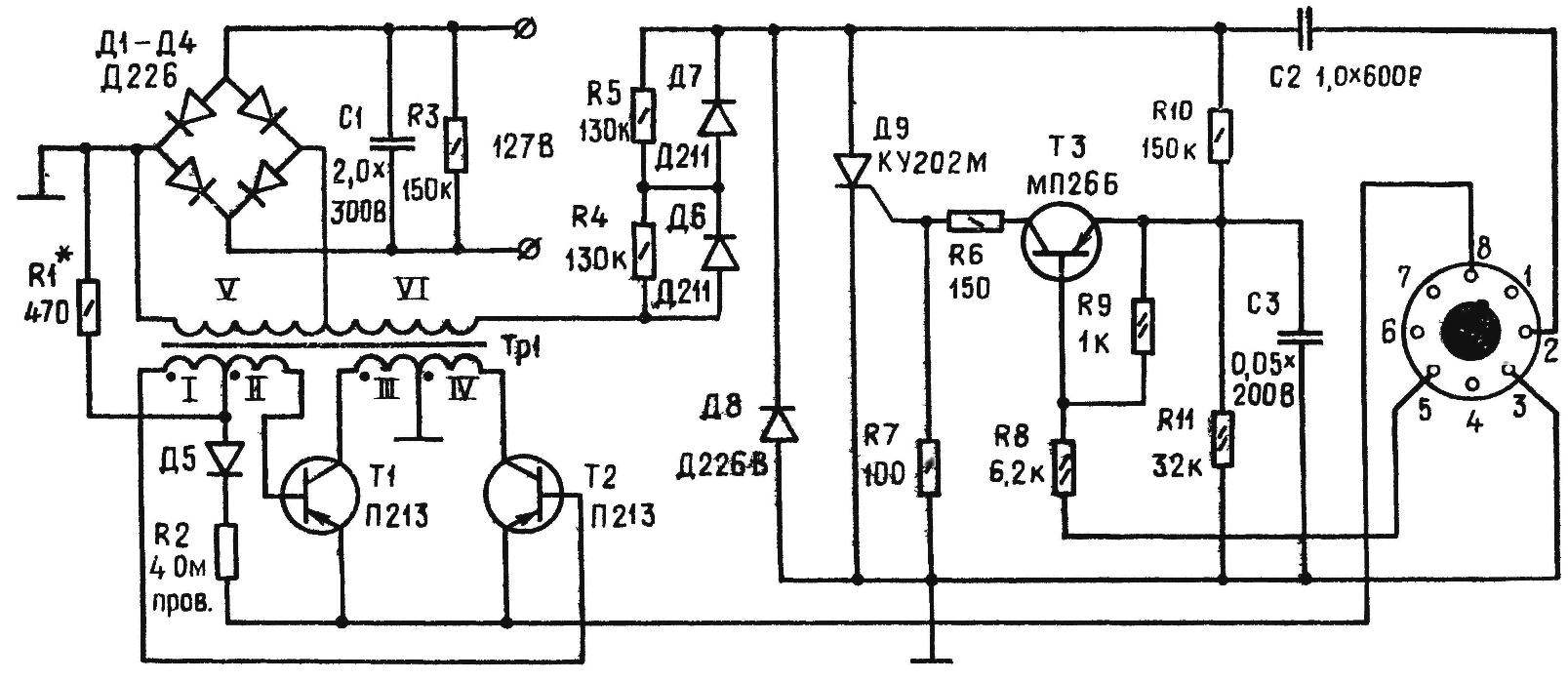
Fig. 1. Schematic diagram of the electronic ignition.
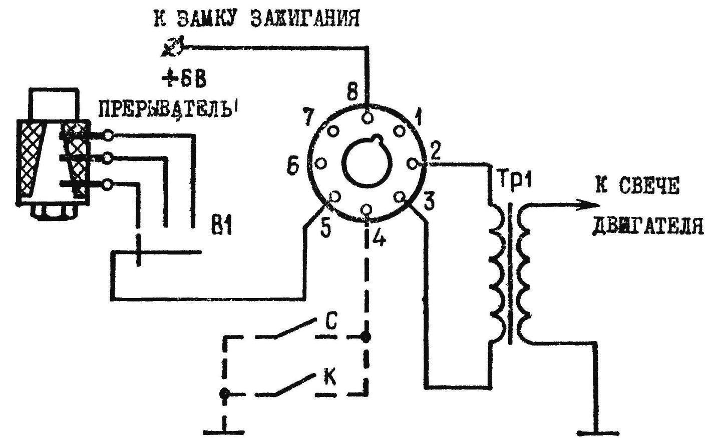
Fig. 2. Wiring diagram for connector to the electrical system of the motorcycle.
The control current of the thyristor is formed in the circuit R10, T3, R6. When the contact breaker transistor T3 opens and the thyristor turns on. As a result, the capacitor C2, the voltage of which is about 450 V, is discharged to the primary winding bobbin. Generates a spark. After turning on the thyristor, the voltage at its anode drops to near 0. At the same time and stops the control current.
Due to the limitation of the duration of the trailing edge of a control pulse, the scheme is stable and at maximum engine speed.
In the scheme of electronic ignition apply the following details. Capacitors Cl, C2 — MBGO, C3 — MBM. Constant resistors — MLT, except for R2, which is wound on the frame of the resistor VS-1,0 nichrome wire Ø 0,2 mm. Transformer wound on the core Ш14Х14 mm, recruited from steel plates. Windings I and II contain 15 turns of wire sew-1 is 0.27, III, IV — 30 turns of PEV-1 to 0.55, V — 640 turns, VI — 1360 turns of wire PEV-2 0,12.
An electronic circuit made by the method of three-dimensional mounting on an aluminum chassis. It is installed in the trunk where motortechna. Electronic ignition is connected to the electrical system of the motorcycle through the connector: socket and socket from octal tubes (Fig. 2).
If necessary, you can go to a conventional ignition system in a socket connector instead of the old base from the bulb insert new lintels (Fig. 3). Thus it is necessary to install the breaker and still as new only works with the electronic circuit.
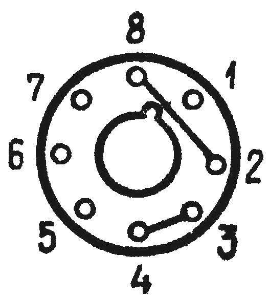
Fig. 3. Adapter.
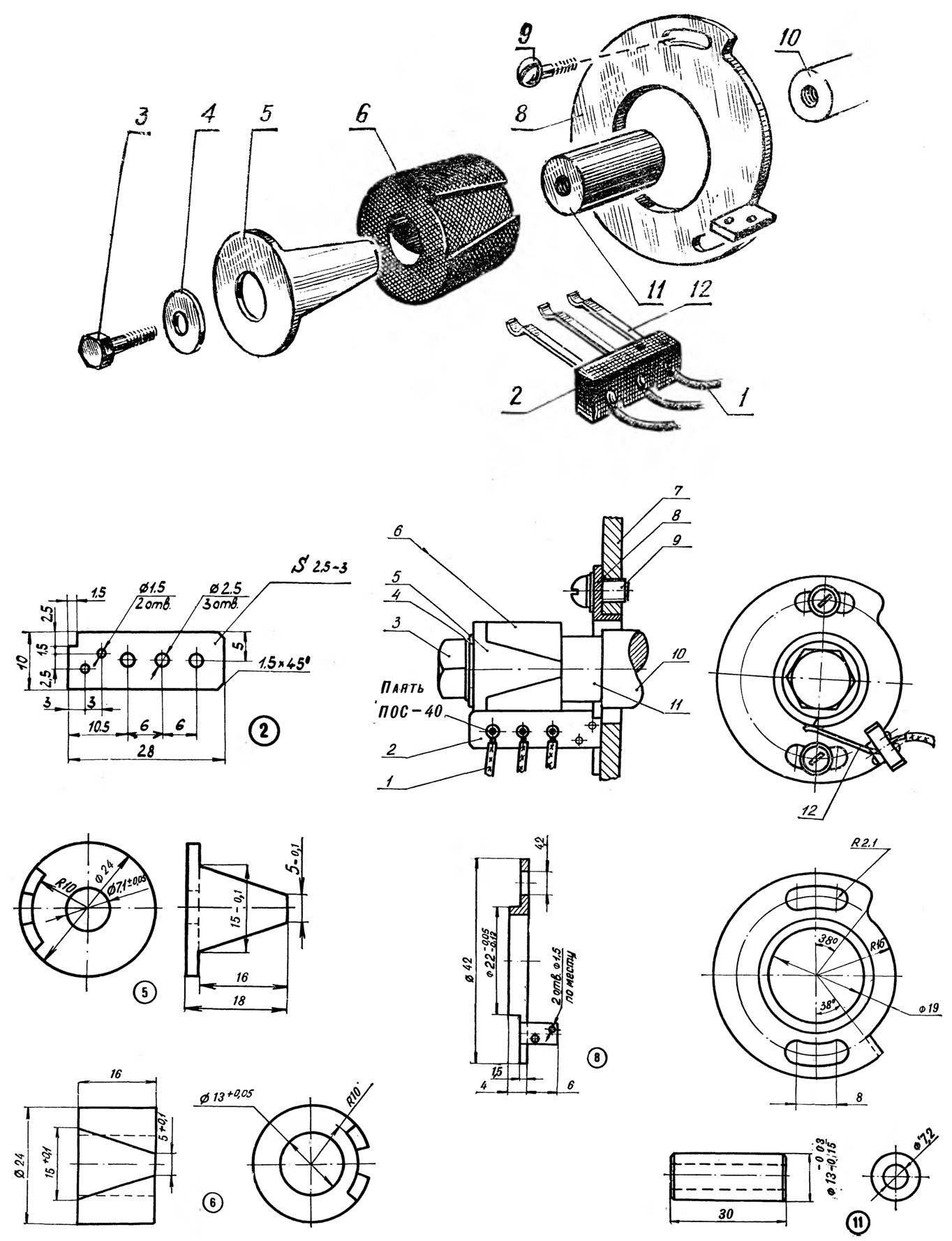
Fig. 4. Device breaker:
1 — lead wire, 2 insulation plank (PCB), 3 — screw 4 — washer 5 — lamel (bronze), 6 — bushing (PCB), 7 — frame, 8 — base (steel) 9 — M4 screw, 10 — crankshaft 11 — axis (bronze), 12 — brushes (steel).
The device of the breaker in figure 4. The rotor is mounted on the axle of the crankshaft instead of the Cam. The base is installed on the seat of the old breaker. On the basis of a limb, which is riveted to the insulating bar. It mounted brushes, which are made from bends. Brushes made of steel wire Ø 0,8 mm.
The rotor consists of an insulating sleeve in which the groove is made in the form of lamellae. The lamella is mounted in the groove of the sleeve with glue BF-2. After the glue dries, the outer surface of the rotor lathe to Ø24.±0.5 mm.
The spark occurs when the contact breaker. The closest to the body of the brush ensures a late starter. It is necessary when starting the engine. Medium brush is used for all modes except mode of motion with great speed on a good road. In the latter case, use extreme brush that ensures the most spark advance.
The reversing motor is as follows.
Locked the back wheel and squeezed the grip includes a first transmission. Install early ignition, and by incomplete inclusion clutch motor slows down. At some point when this occurs, the reverse the engine: the inertia of the flywheel is not enough to overcome the pressure in the cylinder from developing too early in the outbreak (the phenomenon of bestowal). This point is clearly felt. Immediately you need to squeeze the clutch, add gas and switch the ignition to the middle position. Contact closure happens on the other cut half rings and the engine will run normally in the opposite direction. In this case, the warning light lights up red indicating that the battery is not charged. Reverse the reverse can be done the same way or with the engine off, start it again. While the charge indicator lamp will go off again.
Such a circuit breaker is operated for the past three years on motorcycles IZH-56 “IZH-Planeta”. In terms of variety of roads and off-road with repeated use of the reverse run with electronic ignition — more than 20 thousand km.
N. BOGDANETS, Rubtsovsk
Recommend to read
 HAMMER IN THE MAIL
Of all the impact tools — an axe, a sledgehammer, a pick, and others more in the process suffers hammer: slip a large nail or chisel is not lost on its wooden handle. To protect her from...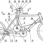 “ROWING” DRIVE VELOMOBILE
Olympic games were held in Greece. I like venoconstrictor, pleased with the success of our riders on the track. And was impressed winning four rowers on academic Powerful boats, rowing...
