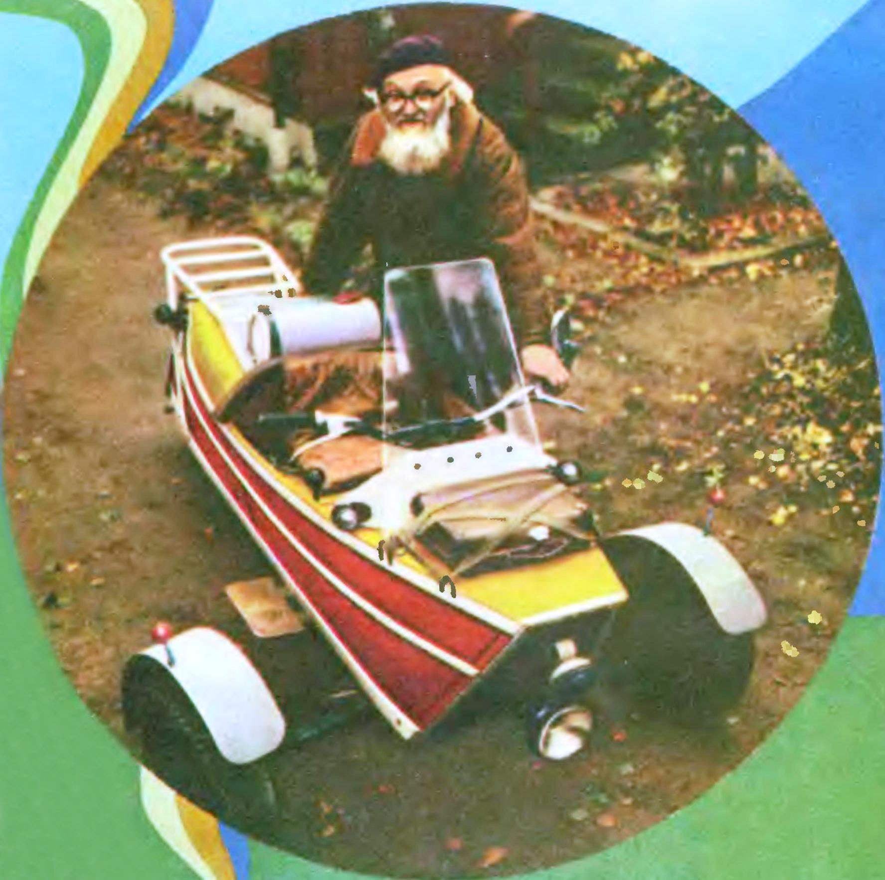
 Doctor of technical Sciences Professor A. G. Ignatov enthusiasts of technical creativity known as the author of a number of original designs of micro cars, party contests and demonstration runs of homemade vehicles. The appearance created machines always arouses keen interest. Not to say that these designs are technically refined or Shine external perfection. Far from it: Professor A. G. Ignatov always strives to use the most available materials, but to get the maximum beneficial effect. Here is his own formulation: “I need mechanical undemanding pet. Unpretentious, like a mule. Avtomol. Perhaps better not say. Don’t need beauty need high performance, reliability and endurance. Don’t need comfort — I need the utility and simplicity of management. Don’t need high-quality and expensive finish you need a good resistance y resistance of coatings, requiring minimal maintenance and expenditure on maintenance and repairs.”
One such machine has been shown by Professor Ignatov on the competition in Moscow in 1966. Even got a special prize For “funniest car.” And funny, by the way, in addition to appearance, there was nothing. But there were many instructive and useful for all “homebrew”, especially beginners. Our magazine has very in detail told about this machine and its Creator (see # 11 and 12 for 1967, article titled “My pet”), And today we will acquaint readers with a new original design of A. G. Ignatov — three-wheeled micro-car, only, rather, a motorized “Robot”. In design and execution it differs significantly from the previously described tricycles, and familiarity with the “Robot” will be useful for every enthusiast of microautomation regardless, he will be this car again or not.
Tricycle Robot made in the home under the engine of the scooter “Tula 200”. Designed for one person and the load of 15-20 kg.

Fig. 1. The scheme tricycle:
1 — clip the front trunk, 2 — the speedometer 3 — windscreen 4 — shift lever, 5 — seat, 6 — fuel tank 7 — engine 8 — visor ventilation matousek, 9 — hatch matousek, 10 — flap rear wheels, 11 — removable flap, 12 — rear rack, 13 — turn indicator 14 — number plate, 15 — brake lever, 16 — jet thrust, 17 — day, 18 — leash switch gear 19 — thrust of the switch, 20 to the muffler 21 — tie rod, 22 — fry, 23 brake pedal, 24 — headlight, 25 — beeps.
Built tricycle (Fig. 1) and in accordance with the terms tehnicheski GAI. In particular, the open type wheel is adopted on the basis of “Rules of the road”, was introduced in January of 1973, which says that a three-wheeled vehicle weighing less than 400 kg are equal to motorcycles.
FRAME AND SUSPENSION. Carrier element of the structure is a wooden frame (Fig. 2), the stiffness of which is provided by the floor, the two solid transverse bulkheads and one web frame. Sticks pine floors and bulkheads — plywood with a thickness of 7 mm. In its lower part of the bulkhead supported by dural angle 40X40X3 mm. Assembly of frame parts — on glue and screws. Detachable nodes are attached with bolts.
Directly to the frame rigidly attached to the springs: front transverse and rear (two longitudinal) — chetvertichnye. On the front spring ends of the fixed axle of the steered wheels, on the back — ears, through which passes the axis of the drive wheel.
For the manufacture of springs used the leaves of the old leaf spring car “Pobeda” (cross-section 45X6 sheet,5 mm). Number of sheets: front — five (olyt showed that if the crew is not overloaded, enough for four); and the rear leaf springs — two pieces and each.
The SWIVEL pins (Fig. 3) front wheels — own design. The friction pair in the node of rotation of axles: bronze sleeve 7 and the steel pipe 3. Sleeve tied to pin 4 and nuts 5 well counter; LRI this hex head of the lower sleeve includes a hexagonal hole of the turning lever 19, thereby providing slide it between the bushings and the bracket 2.

Fig. 2. The design of the chassis.
Fig. 3. Knuckles:
1 — axis, 2 — clip, 3 — (pipe gas 1/2), 4 — pin (pin M10), 5 — nut 6 — washer 2 mm thick, 7, 20 — Bush (bronze), 8 — a press maleika, 9 — solitaire (steel thickness. 3 mm), 10 — deck (steel thickness. 4 mm), 11 — bolt M8, 12 — strip (steel 20X5), 13 — root leaf springs, 14 — second root leaf, 15 — radical leaf, 16 — plank (steel (20X5), 17 — bushing 18 — bolt M8, 19 — pivot arm, 21 — Klondike (steel thickness. 3 mm).
Fig. 4. The design of the frames.
Noteworthy is the attachment of the axles to the spring. Bolt 18 through the sleeve 17 presses the main root sheet to the area of the axle 10. Sleeve 17 freely enters into the elliptical hole in the second radical sheet so that the sheet can be moved longitudinally. The through-bolts 11 earrings scontrini well and do not compress spring leaves tightly, allowing longitudinal relative movement as both indigenous and radical worksheets.
WHEELS: front of the scooter, back from the sidecar of the Serpukhov plant. Rear selected the large size compared to the front for better flotation lo soft ground.
BODY boat construction: wooden slats, the stringers attached to the bulkheads and transverse frames. Bottom of stringer — reinforced, based on the frame throughout its length, and rear console covers (on body length) wheel. The sheathing body is of iron sheet (0,4 mm). On top of the sheathing are missed additional stringers: thus, the casing is sandwiched between them. In the casing body on the right side predusmotreno closed the hatch access opening and the breaker of the ignition system. On the right side of the body placed footrest, to facilitate the landing of the driver.
It should be noted: when designing the casing body supposed to do is not metal, and plastic, or linoleum, to avoid noise vibrations. However, in this embodiment, in places, not tight enough compressed stringers, plating vibrated. Required to install additional bolts to tie exterior and interior stringers.
Seat wooden rack, of a width of 550 mm. the space under the seat ispolzovano to install the battery pack and store tools.
Two trunk: front and rear. The latter is welded from gas pipe 3/8″.
On the rear mounted fold-down stand (to support the body when removing the rear wheel) and handle, which serves as for the body lift, and for “reversing”.
THE POWER PART. Engine “Tula 200” is mounted in a separated compartment collected from three bars removable pad. To the main frame 5, the pad is attached with two bolts M-8. The muffler from the “Tula” is located under the body. Connecting exhaust pipe redone.
Any alterations to the engine were not exposed. The air intake placed under the body. The outlet of the cooling air is through the hatch in the upper part of the body. As experience has shown, cooling even on hot days is sufficient. Starting the engine — electric start or handle, the lever of kick starter. Lever kickstarter respectively rotated axis 180°.

Fig. 5:
1 — transverse spring suspension front harness, 2 — left tie rod 3 — steering the plow, a 4 — pedal foot brake, 5 — front hollow frame hull (transom), 6 — beam, 7 — beep 8 — the right front wheel, 9 — bracket splash guard 10 splash guard 11, a pointer size, 12 — P-shaped bracket for securing Luggage, 13 — below deck stringer, 14 — combined sidelights, 15 — steering shaft, 16 — control handle throttle, 17 — windshield 18 — Central part of the steering, 19 — shift lever 20 — clutch lever, 21 — arm main frame, 22 tank, 23 — visor ventilation of the engine compartment, 24 — warm air coming from the engine compartment, 25 — shield of the rear wheel, 26 rear (driving) wheel, 27—, rear Luggage rack, 28 — turn indicator, a 29 — rear transom, 30 — axle rear wheel, 31 — brake lever, a 32 — rear longitudinal leaf spring, 33, 39 — brake cable 34 — carb, 35 — switch lever gear, 36 — thrust pereklyucheniya gear, 37 — control cable carb, the 38 battery. The number of side stringers in the figure is reduced for clarity.
The drive to the rear drive sprocket by a chain, the tension of which creates an auxiliary roller Ø 100 mm, pressed by a coiled up spring. Such a device was necessary because, due to the very elastic suspension wheel circuit or over-stretched, or so weakened, that came off subcateg.
CONTROLS. The wheel motor extended through the insert; its overall width is 900 mm. All the controls, alarm button and light switch is used without change.
The steering column ends with a bipod, to which by means of ball joints С3А attached to the ends of the split transverse thrust, a member of the “trapeze Jeanty”. Transverse thrust — also from motorized С3А. Ratio “steering — wheel” is close to one.
BRAKE SYSTEM. Is the main brake on the rear wheel. The brake pedal is connected to a steel cable Ø 5 mm with lever Cam drum brakes. The cable is hidden and the handset. Brake drum and pads homemade: drum diameter 180 mm, width of pads of 45 mm.
After the “traffic Rules” was specified permissible maximum braking distance for motorcycles with a sidecar of 8.2 m, on the right front wheel had a hand brake of the scooter “Vyatka”. This brake proved useful when Parking on an incline.
The brake light switch is connected directly to the brake pedal. The gear shifting is manual. The operation of the clutch and the carb — on the steering wheel. Button the enrichment of the mixture is near the dashboard.
On the dashboard mounted speedometer and separate toggle switches for the big lights, sidelights, turn signal, ignition, and starter button. There is a General switch, disconnecting the whole system from the battery. Relay-regulator — from the “Tula.”

By the time of publication tricycle passed more than 2500 km Problems, with the exception of jump-out circuit, are completely eliminated after the installation of the tension pulley was not. Operating speed on a highway is 40— 45 km/h. a Maximum of 63 km/h. the Machine is mild on the go and well “holds” the road. Passability on bad dirt road no worse than a conventional car, but with the deep ruts of the drive difficult. However, small specific pressure ka the ground and greater resistance allow you to bypass the bad sectors on the sidelines. On snow-covered road, the car goes bad.
Obviously, this sample can be built and double tricycle; place, depending on the length and width can be located or one behind the other (tandem), or next (the final location will require a very rigid frame, able to perceive a torque when asymmetric load).
Take this opportunity to appeal to the readers (regardless of their age). Go ahead and build! There is no interesting process of creation! Even if it ends on paper.


