
The homemade microcar “Laika” is a frameless all-metal construction. Despite its small size and simplicity, the car provides comfortable seating for two people (driver and passenger), has two trunks, is sturdy, and maneuverable. Thanks to its low weight, high body, low engine power, relatively small wheels, and rear-wheel drive, Laika’s off-road capabilities are quite high. The rigid lifting roof with side flip windows reliably protects from the weather, and the engine-heated windshield ensures good visibility even in winter.
“Laika” is built according to the traditional scheme for microcars: the engine (from C3A) is in the rear, and the driving wheels are at the back. All units are suspended from the load-bearing body. The drive and cross levers are taken from C3A. The main transmission is from the TG-200 scooter. The electrical equipment is six volts. The battery is alkaline, 45 watts; the cells are assembled in the form of a flat package and installed along the side of the car.
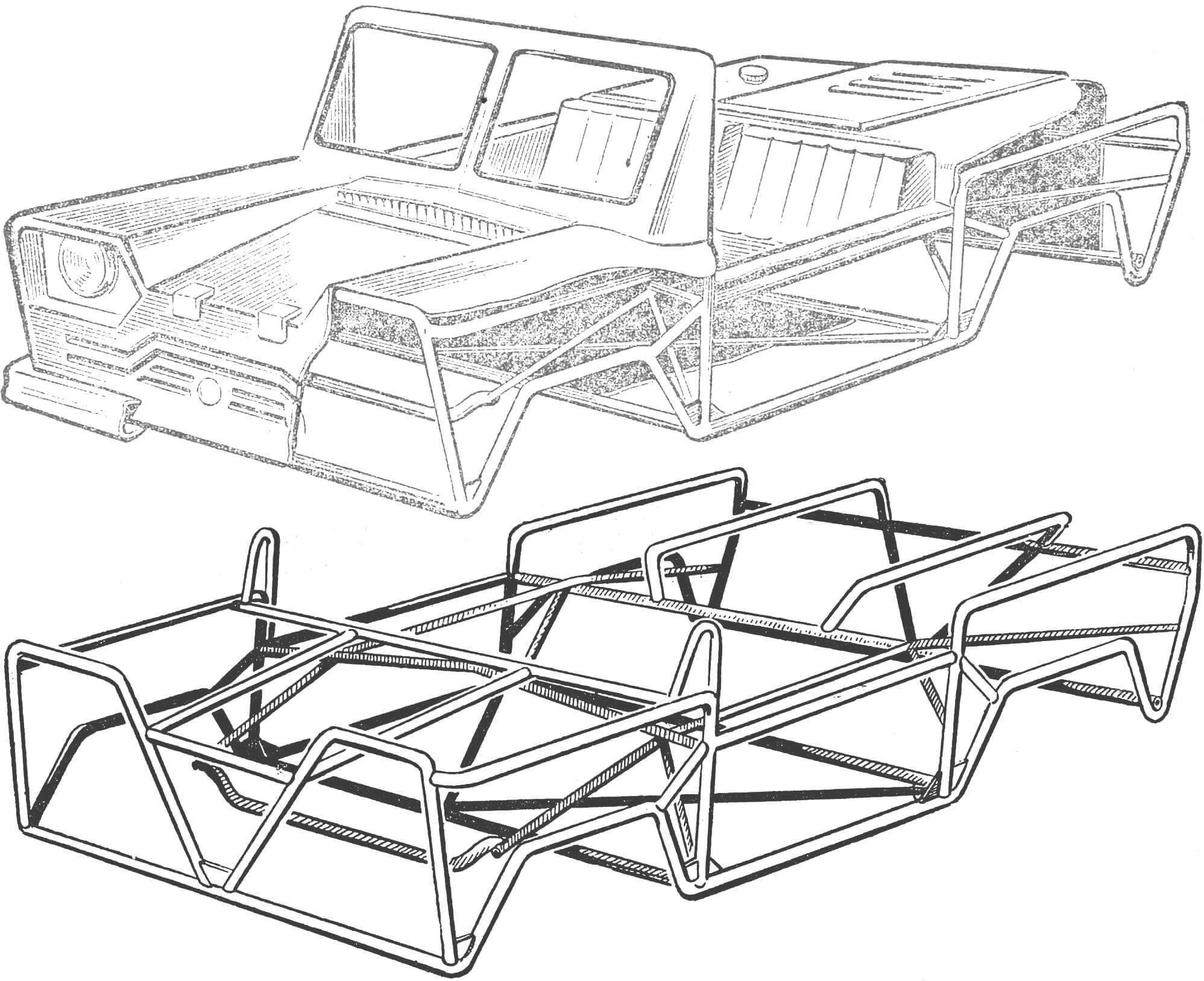
The body consists of a frame, cladding, windshield, rear window, lifting roof with side windows, and seats with a backrest. It is equipped with a horn, windshield wiper, rear-view mirror, control instruments, battery, fuel tank, and engine control mechanisms. Attached to the body are: front suspension with steering mechanism and steering column, rear suspension with brakes, power unit consisting of an engine and main transmission with a differential.
The frame is mainly welded from 1/2″ pipes. (It is advisable to use thin-walled pipes up to chromansile pipes. In this case, while maintaining the same strength, the weight of the frame can be reduced by half.) Templates for bending are made from 3–6 mm diameter wire according to a 1:1 scale drawing. The cross member of the front suspension attachment is made from a 1″ diameter pipe, and the cross members of the rear suspension attachment are made from a 3/4″ diameter pipe.
Before welding, the frame is assembled on a flat surface, and the pipes are tied with 1–2 mm diameter wire through pre-prepared technological holes. In the joints of the pipes after welding the frame, reinforcing braces are installed and welded, made of 2–3 mm thick steel, with dimensions of 100×100 mm. The braces for strengthening the joints in the transverse direction are double, P-shaped, with dimensions of 100×200 mm.
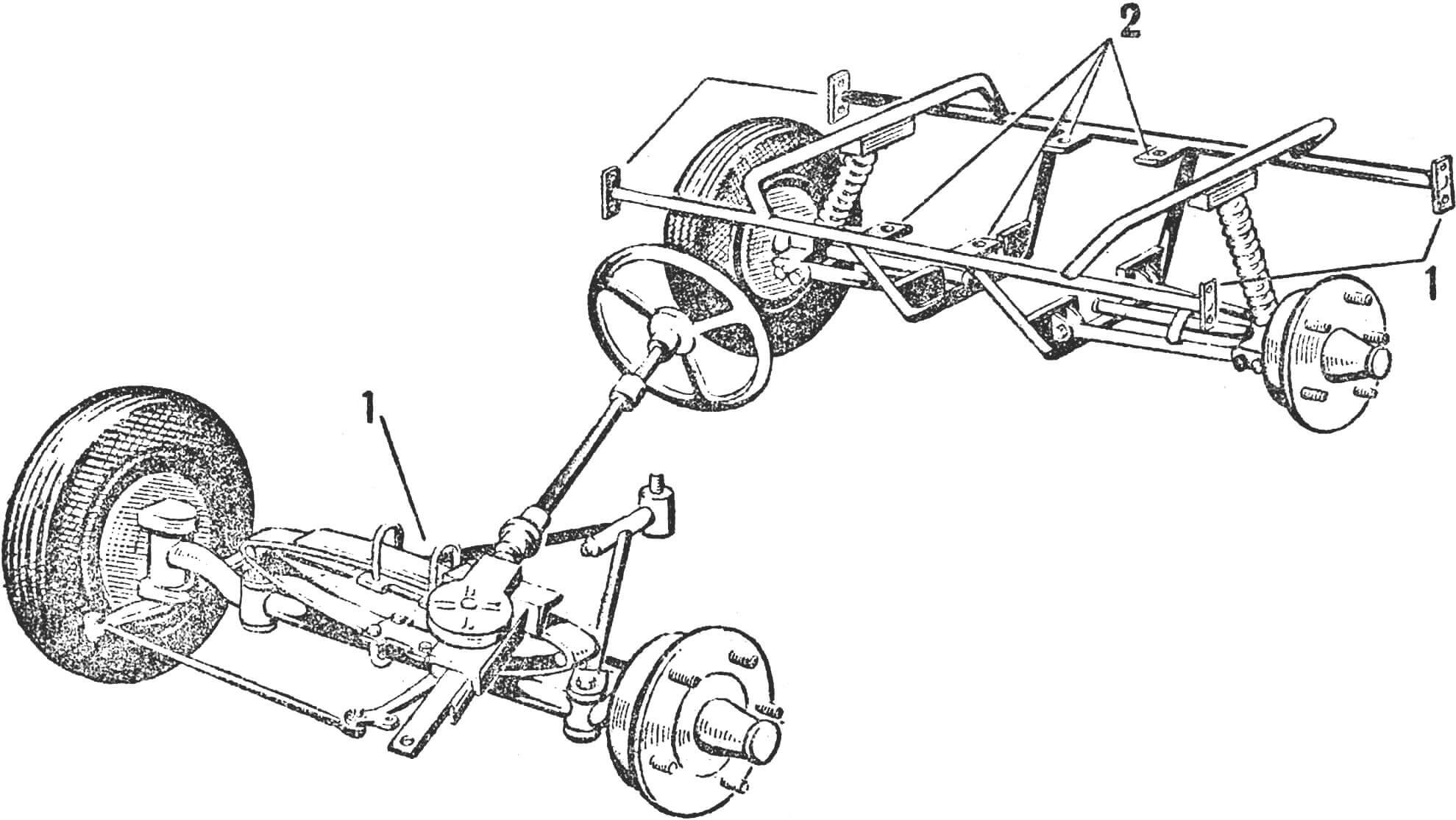
1 — suspension attachment points to the body; 2 — subframe attachment points.
Rubber pads above the headlights serve as bumpers. They are made from cut hoses and put on the joint of the panels. The pads are attached with M5–M6 bolts. All cladding panels are attached with M6 screws with semi-hidden heads.
The windshield and rear window are taken from the GAZ-51 car along with the frame. The frame is cut from the inside along the middle pillar, slightly straightened (the resulting gap is welded), and installed upside down. The seal is trimmed. In the absence of a standard seal, you can use a rubber tube with a diameter of 10–12 mm. The tube with a threaded wire with a diameter of 0.5–1.0 mm inserted into it is placed in the frame groove. The ends of the wire are tightened and secured. The frames are attached to special profiled brackets-posts with 5 mm screws.
To protect against vibration, the frames are reinforced along the upper edge with angles made of steel 1.5–2.0 mm thick. The windshield and rear window are connected by a special rod made of thin-walled pipe Ø 20 mm and attached to the angles with M6 bolts.
The rod that connects the windshield and rear window is linked to a hinged roof with side windows that tilts upward on a hinge. The car widely uses soft “hinges” – strips from a rubberized belt, clamped between the panel and the overlay and tightened with M5 bolts. These hinges are also used to attach the trunk lid and side windows. The latter are cut from 4 mm thick acrylic glass. The left one is made with a slightly larger opening and therefore does not fully cover it; thus, we meet the requirements of the technical conditions for a sliding window on the left side. The windows can be tucked under the roof in good weather. If desired, the roof, along with the side windows, can be easily removed by disconnecting the rod from the windshield and rear window.
The front suspension (Fig. 1) of the microcar “Laika” I built consists of a beam with spindles and hubs and a transversely arranged elliptical spring.
The brake disc and drum are taken from the C3A motor scooter (if the wheel size is 5–10″) or from the C1L (for wheels with a size of 4.5–9″). Forged levers of the turning spindles bend in place, and the lever of the right wheel should be double-armed, while the lever of the left one should be single-armed, directed backward.
The drawbar, which takes longitudinal forces, is made of two steel pipes Ø 28 mm. The ends of the drawbar converge on a ball joint 11, for the manufacture of which a part of the steering linkage of GAZ-69 or M-20 cars can be used, along with the tip and lock nut, as the lightest option.
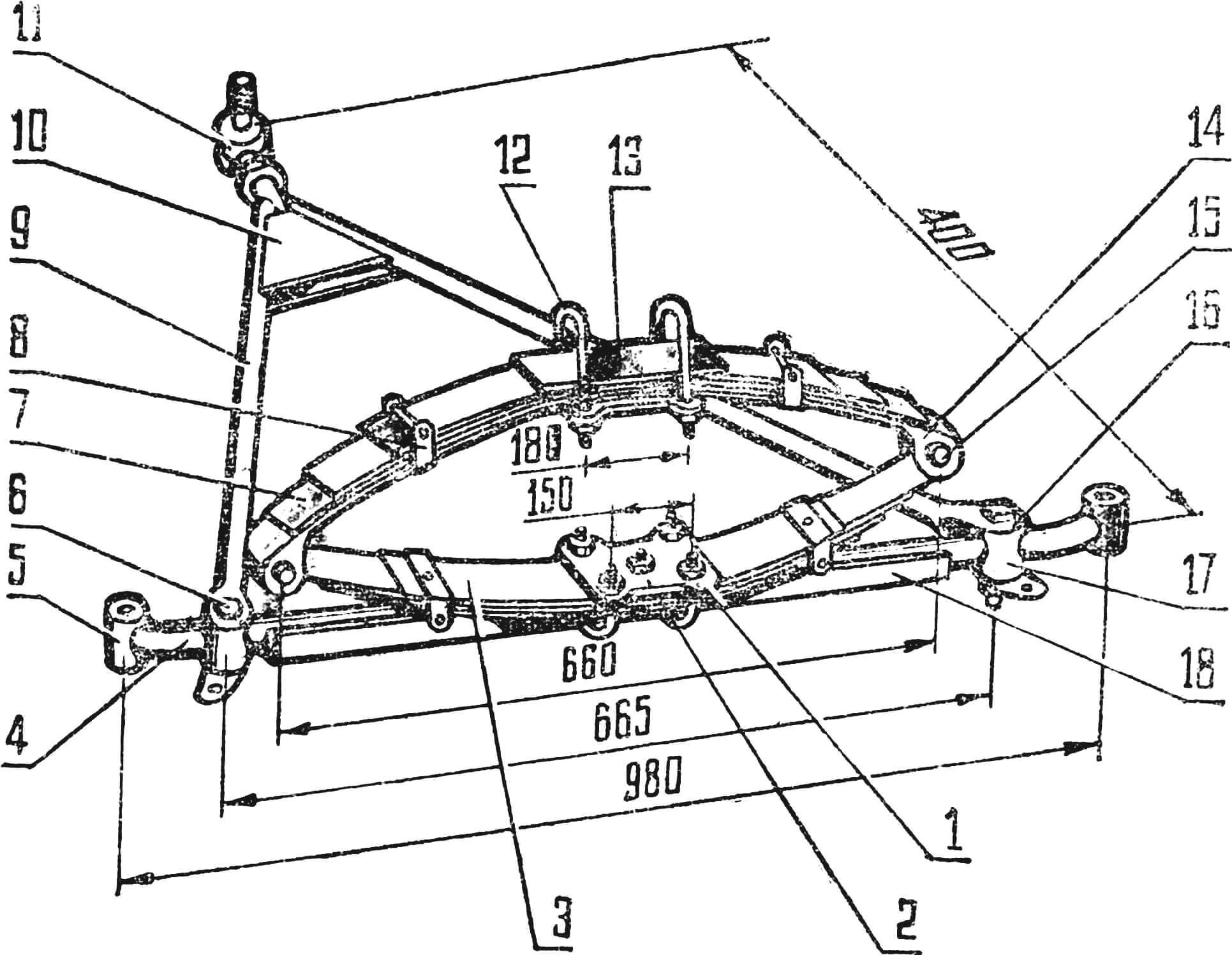
1 — jockey strap; 2 — center bolt of the spring M8; I = 35; 3 — strip for mounting clamps; 4 — beam, l = 845 (pipe Ø 42); 5 — turning spindle fist; 6 — bolt M12, l = 85; 7 — spring leaves; 8 spring clamp; 9 — drawbar; 10 — brace 63; 11 — ball joint; 12 — jockey strap clamp, Ø 10; 13 — lining; 14 — spring tip; 15 — pin M12, l = 90; 16 — drawbar clamp; 17 — bobbin, Ø 50 l = 60; 18 — angle № 5 l = 615.
With the tip, you can compensate for errors made during the drawbar fabrication. The pin of the tip is inserted into the body bracket, tightened with a nut, and secured with a cotter pin.
The free ends of the drawbar are cut with a hacksaw to a depth of 30–50 mm, spread apart, slid onto the brackets 16 of the drawbar made of 3 mm thick steel, and welded to them with a continuous seam. It is advisable to make recesses for attaching the tow cable in the brackets right away.
To make the brackets, it is necessary to assemble the entire suspension beforehand, suspend it to the body, and make templates from cardboard or sheet metal according to which to cut and bend the brackets themselves.
The brackets are attached to the bobbin with tension bolts M12 (6).
The spring is assembled from two semi-elliptic springs connected by pins 15. It is preferable to use its leaves 7 from GAZ-69, M-20 cars, as they are light and strong enough. The curvature of the spring leaves should be slightly increased by rolling them through the proper rollers or simply hammering them.
Protrusions with an inner diameter of 30 mm are made at the ends of the lower main leaf. The protrusions should be bent in a hot state, avoiding hardening. Two holes Ø 8 mm with an external countersink are drilled at the ends of the upper main leaf for attaching spring tips.
The deflection of the assembled spring without load should be approximately 270 mm. Each spring consists of 3–4 leaves. The spring leaves are tightened with a center bolt M8 (2), which also holds the jockey strap cushion 1.
In addition, two clamps 8 are placed on each spring, made of a steel strip 20X3 mm and attached to an auxiliary strip 3 made of roofing iron sized 400X45X0.5 mm. This is done to avoid weakening the spring leaves with additional holes.
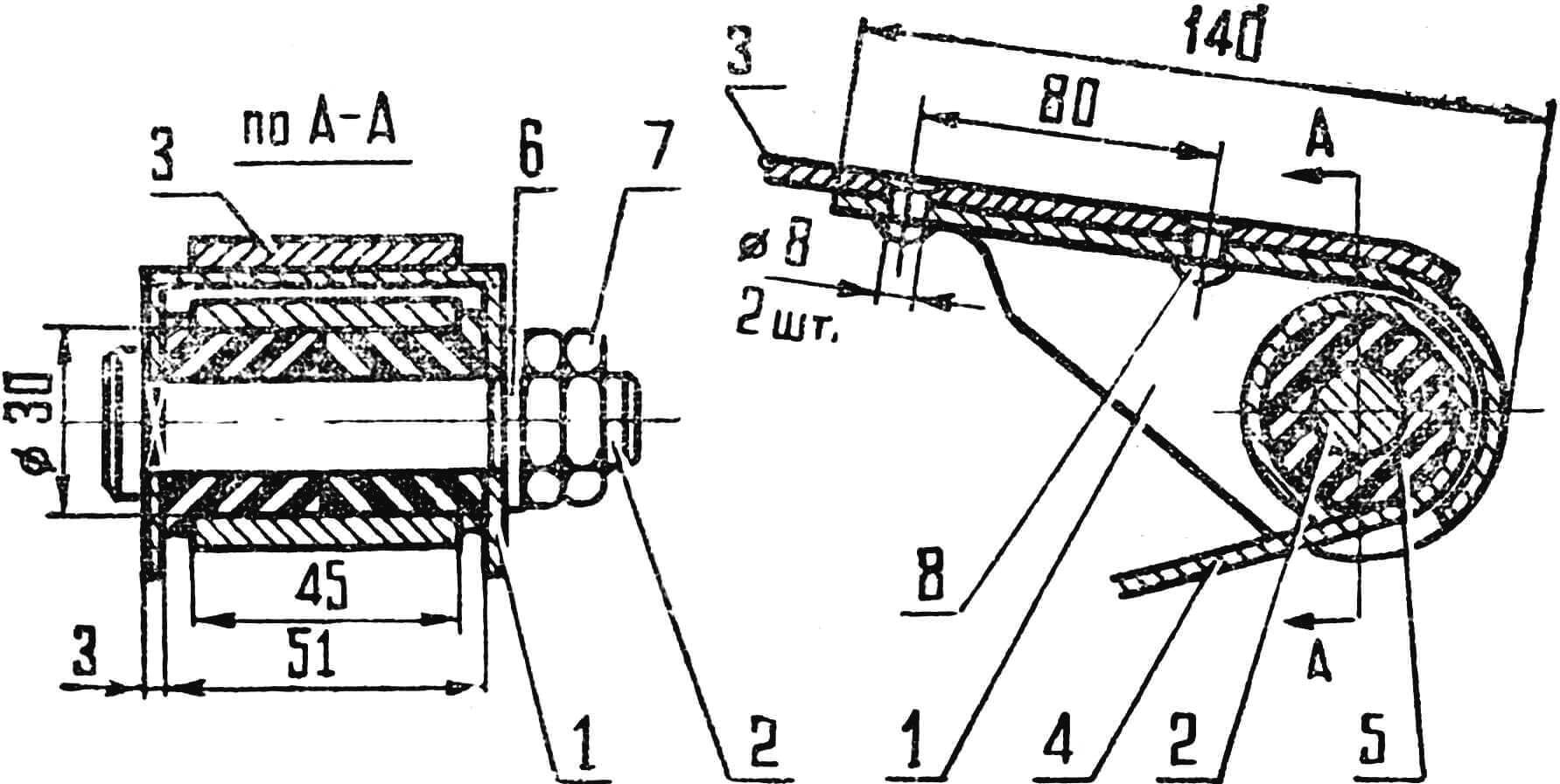 FIG. 2. SPRING TIP:
1 — tip casing; 2 — thread rod M12; 3 — upper main leaf (from GAZ-69); 4 — lower main leaf (from GAZ-69); 5 — bushing; 6 — washer M12; 7 — nut M12; 8 — rivet.
The upper and lower springs are connected to each other (Fig. 2) by a spring tip 1, a pin 2 through connecting rubber bushings 5. The tip is made of 3 mm thick steel, bent and welded with a solid seam. A square hole 12X12 mm is made in one cheek of the tip, and a round hole Ø 12 mm in the other. The square hole is necessary so that the pin does not rotate in the eyelet during the spring operation. It is advisable to cement the pin to a depth of 1–1.5 mm.
Rubber bushings are used from the M20 car. But they can be made on a lathe or simply with a knife with subsequent processing on an emery wheel. The bushings should be made slightly larger in diameter than the eyelet diameter, and the hole should be smaller than the pin diameter. This will provide tension and prevent rotation both in the eyelets and on the pins.
The spring is attached to the front axle beam and the body crossmember with two clamps made of a Ø 10 mm rod.
FRONT AXLE ASSEMBLY
The cores are pressed into the ends of the beam so that their ends protrude by 25 mm. Hubs with a 6° tilt are welded to the inserts. The inserts with welded hubs are pressed onto the protruding cores of the beam, dowels are inserted into the hub holes, and by rotating the inserts, the dowels are set at an angle of 2°. After setting the dowels, the insert and the core are welded to the beam. Solidol for greasing the dowel will be stored between the insert and the core.
INSTALLATION OF WHEEL GUIDES
Camber in the vertical plane is provided by installing spindles with an axis tilt. When the wheels are cambered, the distance between the axle of the kingpin and the point of contact of the wheel with the road decreases, making turning easier. The camber angle of the wheels is maintained within the range of 0–2°.
Toe-in in the horizontal plane is achieved by changing the length of the transverse steering rod. The toe-in, measured as the difference in distances between the wheels at the front and rear edges of their circumferences, is within the range of up to 12 mm.
The longitudinal tilt of the kingpin is provided by installing the front beam with a slight tilt. This is done for the stability of the wheel guides in the middle position. The longitudinal tilt angle of the kingpin is maintained within the range of 0 to 3.5°. The smaller this angle, the easier it is to steer the car.
The transverse tilt of the kingpin to increase the stability of the wheels in the middle position is provided by the corresponding shape of the front beam. The transverse tilt angle of the kingpin is 6–8°. Smaller values apply to wheels with a smaller diameter.
It is advisable to install shock absorbers and limiters on the suspension using telescopic shock absorbers from MZMA, IZH, or, in extreme cases, friction shock absorbers from C1L. The lower eye of the shock absorber is attached to a bracket tightened under the bolt of the strut.
If there is no shock absorber, you can only install a suspension travel limiter in the form of a rubber buffer, fastened on the jockey cushions with the help of overlays tightened under the nuts of the clamps.
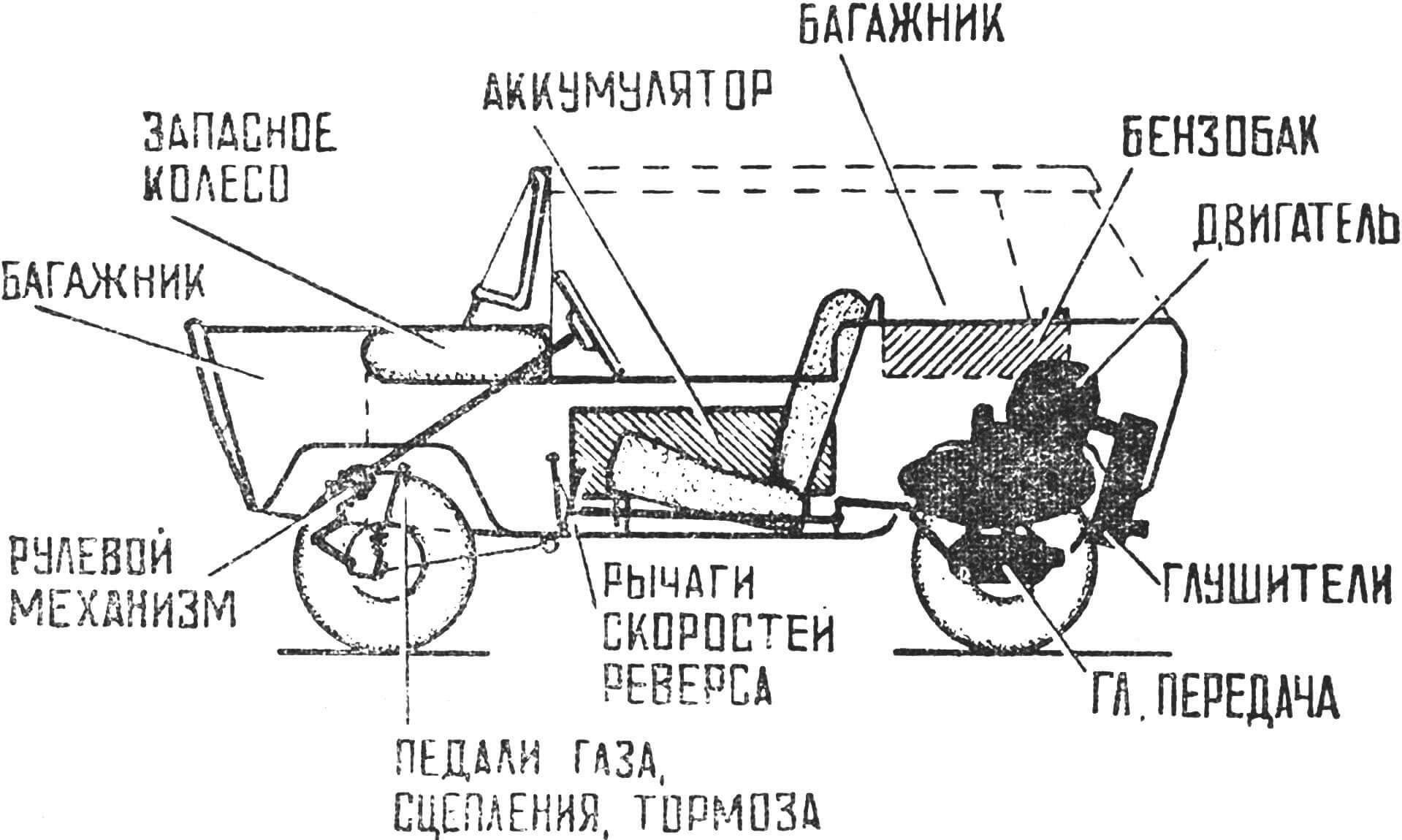 FIG. 3. LAYOUT SCHEME.
Thus, this suspension is easy to manufacture, allows attaching it to the body at one point, has only one lubrication point (ball joint tip), and allows the wheels to adapt well to road irregularities without body tilting.
The camber angle, toe-in, and the transverse tilt of the kingpin during suspension travel remain unchanged.
The control drives for the engine, gearbox, and brakes are combined: a bicycle chain is used on turning sections, and on straight sections, there are rods made of steel wire with a diameter of 6–10 mm. These rods have a device for adjusting tension and eliminating play. Whenever possible, cable control systems should be avoided, using them only where nothing else is applicable. Open cables often jump off guide rollers, which can lead to emergency situations while the car is in motion. Cables in the casing require frequent lubrication and are difficult to access. They should only be used for carburetor control, and even then, only in the section directly adjacent to the engine. Chains work somewhat better. It is even better to use rigid rods and levers.
In addition to the necessary and traditional instruments (speedometer, ammeter, indicator lights for turn signals, parking brake, clock, etc.), it is highly desirable to install a thermocouple to monitor the cylinder head temperature. The IZH engine is located in unfavorable conditions for cooling and observation. The best instrument is a tachometer of the TCD-9 type, compact and not afraid of vibration. The instrument should have a scale up to 35°. The thermocouple for it has a ring that is clamped under the spark plug or under the bolt securing the cylinder head. The thermocouple ring has a hole with a diameter of Ø 18 mm, and the spark plug is Ø 14 mm. To adapt the thermocouple to the motorcycle spark plug, it is necessary to cut a sector from the ring, bend the ring to Ø 14 mm, and weld the narrowed ends. When attaching it under the cylinder head bolt, it is necessary to machine a special copper or brass washer that will press the thermocouple against the cylinder head.
TECHNICAL DATA
- Length — 2600 mm
- Width — 1280 mm
- Height — 1380 mm
- Front wheel track — 1160 mm
- Rear wheel track — 1100 mm
- Wheelbase — 1600 mm
- Engine — IZH-56
- Tires — 5–10″
- Speed — 45 km/h
- Full weight — 370 kg
B. Derkachev, Kinel, Kuibyshev Region
Recommend to read
 KATYUSHA BM-13
Scale model 1:25. THE JET SYSTEM OF VOLLEY FIRE BM-13 "KATYUSHA" ON THE CHASSIS. "Katyusha" — the informal collective name mobile rocket launchers BM-8 (82 mm) and BM-13 (132 mm).... “BOTTOMLESS” BARREL
In the country or the plot is always required to have a supply of water for domestic needs. Keep the tank in the shower or reservoir for watering the plants and filled to the required...
